|
_
Day 10
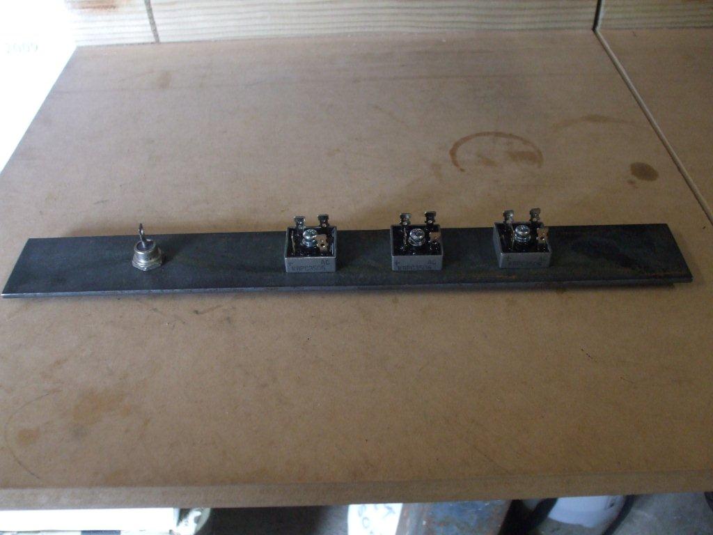
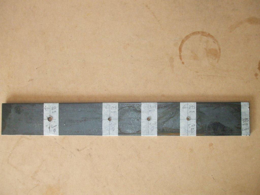
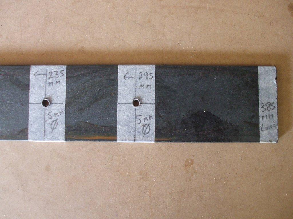
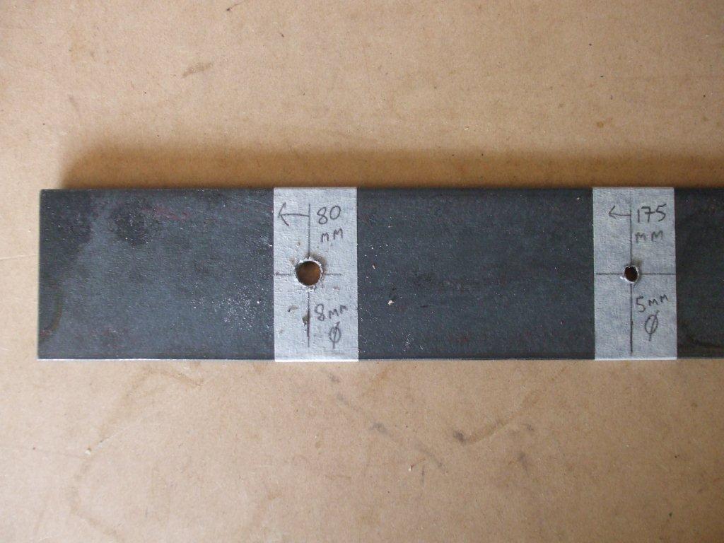
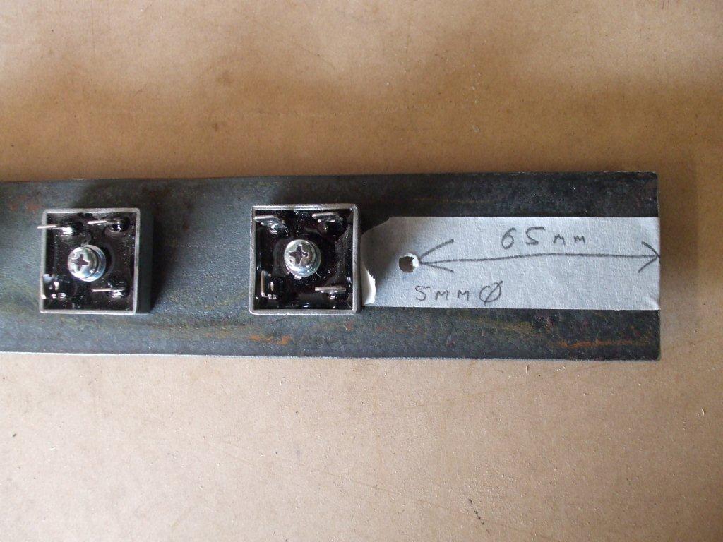
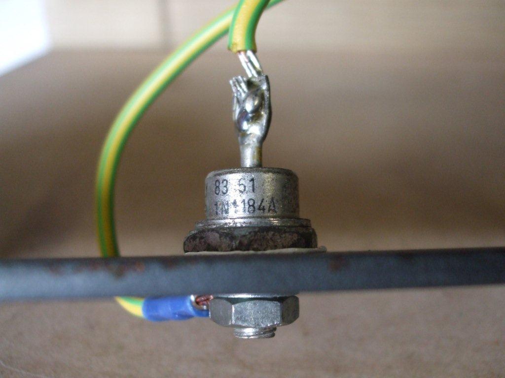
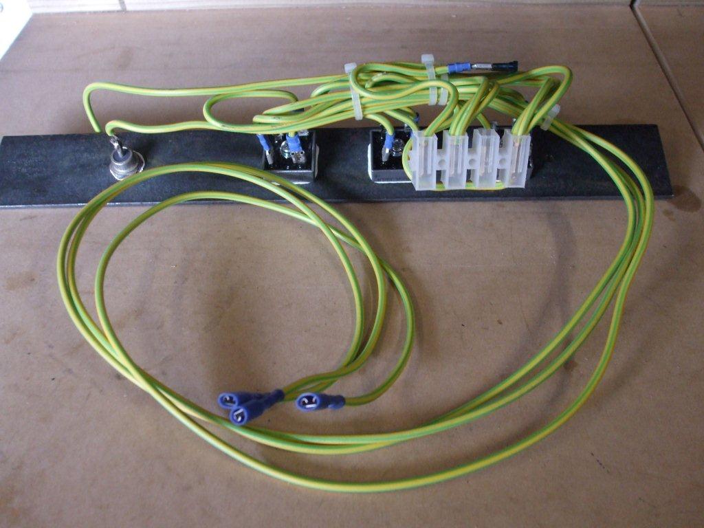
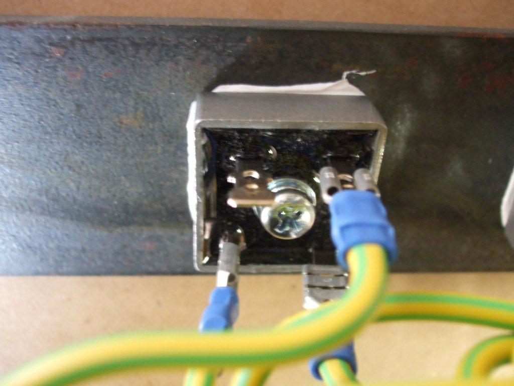
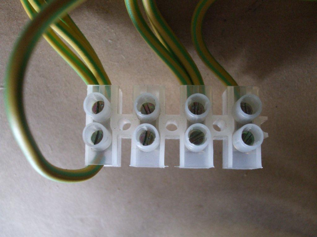
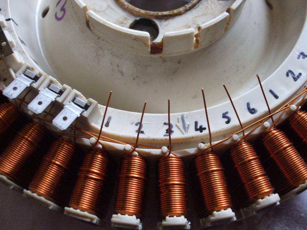
Now for some of that electrical nonsense……………….. Well, with a bit of research & a few trips to suppliers & our local pick a part (car scrap yard), I have some good & bad news. The good news is that I picked up a couple of battery cables from the scrap yard, the bad news is that after spending hours removing different alternators to eventually find one with the rectifiers that I wanted the yard told me they would only sell the entire alternator & would charge me the full alternator price. Oh dear, that would have put me way over budget, so I decided to buy new less expensive single phase rectifiers & wire 3 of them together & also buy the blocking diode new. These parts were not too bad & far less expensive than a second hand alternator. The idea is that a rectifier will take AC & turn it into DC, the motor I have produces 3 lots of AC (3 phases) & so I can add a rectifier to each phase & join the DC outputs up afterwards. There’s lots of other cool stuff about rectifiers & how it can do this with just a few diodes wired together but we don’t need to know this. Update May 2013: We now sell the rectifiers for this project on our Electrical-Electronic Parts page, these new ones are rated up to 50A 1000v. The blocking diode is needed to stop the power in the battery going back up the cable to the motor, it works a bit like a valve & only lets our DC output go one way. Both the rectifiers & the diode are rated at a minimum of 35A & they can produce some serious heat so they need mounting on a heatsink which is just some metal that will dissipate the heat. I’m going to try & use the same 50mm flat bar I used earlier for the heatsink & bolt all the rectifiers & the diode to it & mount that inside the plastic downpipe to keep it out of the weather. I’m not sure how much heat these components will create so I’m going to be guessing a bit on the size of the heatsink but it will be easy to make something bigger if needed, plus they will be outside & only get hot when it’s windy so that should help cool things down. Mounting something hot to the plastic downpipe could be a problem but I’m hoping it never gets that hot. Famous last words, I tried it & the entire turbine melted into one big sticky blob on a stick. Ok, I’m only kidding, but definitely something to look out for during testing. So I’ve cut the 50mm flat bar to 390mm, drilled some holes & mounted the components. I’ve made the length of the bar enough to poke out the end of the downpipe about 50mm, I think I must have scared myself with thoughts of melting plastic so I’m hoping that this will help the cooling. It is important to note that I didn’t insert the flat bar passed the turbine shaft, I kept it about 30mm away from the end of the shaft to stop anything shorting out. A neat idea would be to mount a very small fan blade onto the end of this shaft to help dissipate the heat but I really don’t think it will be necessary. Between the components & the flat bar I inserted some heatsink paste, this was just some I had left over from making PCs. Maybe it comes with the processor or the processor heatsink but I can’t remember. If you don’t have any, do you really need it? Well I think so, it’s a cheap item that can be bought from most PC shops or electronic stores, I remember I use to make this many years ago but I can’t remember what the ingredients were, zinc oxide & Vaseline or something like that, isn’t nappy rash cream mostly zinc oxide, I should look it up & put a link here one day. Now for the wiring….. Using 10AWG or 2.5mm diameter multi stranded wire, this can be carefully cut from some 6mm cable that is normally used for electric showers or stoves etc. This is important or we could be back to that melted blob scenario. I managed to fit my cable onto blue crimps, red crimps being smaller & yellow crimps being larger, again you can get these from all electrical suppliers, they are fairly inexpensive but I think they are important for doing a good job. Update May 2013, we now sell these & many other crimps on our Crimp Terminal page. So I connected 3 wires to the crimp terminals of the motor & wired each one to the AC leg on it’s own rectifier. I ran the cable from the motor down the outside of the downpipe & in through the open end, I had thought of keeping all the wiring inside the downpipe but doing it this way meant I could access it easily at a later stage for maintenance, each wire was 930mm long with a blue crimp on each end. Using the same gauge wire I wired up the 3 rectifiers, joining all the positive DC outputs together onto a connector strip, I also joined all the negative DC output together onto the connector strip. From the positive DC output from the strip I ran a wire to the blocking diode, then through a 30A fuse & back to a separate place on the connector strip. I’m not expecting to create 30A here but this may come in handy in the unlikely event of lightening. Putting a smaller fuse here would be a problem because if it blew in a strong wind the turbine could speed up out of control without an electrical load connected to it with no way of easily replacing it. A smaller fuse will be mounted at ground level probably within the charge controller. I then connected the DC output cable, the one that will run down the centre of the scaffold pole, I connected this to the DC output on the connector block. I will create some simple wiring schematics to show all this. Next I needed to rewire the motor, many of you may be thinking why & also that it sounds complicated. These are indeed good questions, firstly the way the motor is currently wired will produce far more voltage than we need, maybe up to 300v when really we need something around the 12v or 24 v. It is possible to rewire the motor & trade in some of that voltage for current, it gets a bit complicated now but you don’t really need to know why it works as long as the instructions are clear enough on how to do it. Here’s the techy bit that you may want to skip. The motor has 42 separate coils of copper wire wound around an iron core with 14 magnets going past them, each time the magnet passes the coil it will generate a voltage. At top speed each coil can create 21V. The coils are currently wired in 3 groups of 14 in series which can create 300v, actually every 3rd coil is connected together to produce a series of 14. Each group is known as a phase & each group connects together at one end in a kind of star shape if you were drawing it on paper. So the current configuration can be correctly called 3 phase AC in a star configuration. What I’m going to do is create groups of 2 coils in series & wire 7 groups in parallel & connect each phase of 14 in a star configuration, the idea of using 2 coils is that it would still produce 12v even at lower speeds. So all this is great in theory but I spent a couple of hours trying to visualise this on paper of how exactly I was going to do it in practice. Lots of pieces of paper later with little crude pictures of coils on them wired up in some crazy fashion & I think I’ve got it. I’m half way through this now & it is going well, if you can solder then the actual work is not too difficult. |
|
If you like our site then please click on the Facebook icon at the top right of this page, thank you.
For more information you can email us via our Contact Us page.


