
Self Balancing Scooter Day 8
October 31st 2012
2 hours |

|
The build process is almost done so while I wait for the accelerometer/gyro board to arrive I thought I would make a start on documenting how to use & program the Arduino micro-controller.
This is also my first time so I will try to cover the basics as best I can but there are many other resources out there written by much more experienced people than myself.
This is also my first time so I will try to cover the basics as best I can but there are many other resources out there written by much more experienced people than myself.
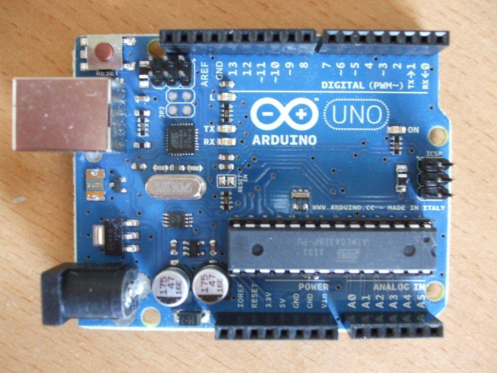
Above is what the Arduino board looks like. The exact name of the board is an Arduino Uno R3 USB, the R3 being the latest version as of October 2012.
There are many types & many versions of each type, there is the official Arduino version made in Italy which is shown in the pic above & there are copies that work just as well but the most common board & the easiest place to start is by using the Uno.
Some of the other Arduino types have strange names such as the Mega2560, Duemilanove, Leonardo or Diecimila, some of these have more memory or more input or output ports but the Uno seems to be the most common.
There are other circuit boards that are designed to work with the Arduino & these boards are called shields, they would be referred to as adding a wireless shield or adding an ethernet shield. But all we need is just the plain old Arduino Uno.
You can pick up the official Arduino Uno R3 USB in America for around $29 USD so if this is your first time then definitely start there.
Most online information & downloadable code will be written for this board so for only $29 it is the perfect micro-controller for this project.
You can purchase it with or without the USB cable, mine arrived without one but it is a fairly standard cable normally found on USB printers.
So I opened the packaging & looked at this nice new shiny board, to be honest I had no idea what to do next.
So I went to the Arduino website http://www.arduino.cc
I strongly suggest you start at the Arduino website & click on Getting Started, this will guide you through downloading the software. It then takes you through a short tutorial on how to load a small program onto your Arduino via the USB cable that makes an on board LED flash. This may seem simple but it was exactly what I needed.
This would be a good time to point out that the Arduino code is called a sketch, so when I talk about downloadable code & uploading code or a program to the Arduino I should really be downloading & uploading a sketch.
Now I've got the software & I've just learned how to load a program & upload it to my Arduino so I'm now ready for something bigger.
I'm not going to reinvent the wheel here, I'm going to use version 3 of a self balancing program I found on this website: http://www.rediculouslygoodlooking.com
You can download it below, just copy it from the word doc or text file below & paste it into your Arduino software, verify it & upload it to your Arduino board, it really is that simple.
Both the files below are in a standard text format, pick which ever version suits your gyro/accel combo board, there's more on this on the Day 10 page.
| arduino_program_for_self_balancing_scooter_v3.txt |
V3 is the original code designed for the IDG500 Gyro & the ADXL335 Accelerometer.
V4 code is the same as V3 but tweaked to work better with my IDG655 gyro & ADXL335 Accelerometer.
V4 code is the same as V3 but tweaked to work better with my IDG655 gyro & ADXL335 Accelerometer.
| arduino_program_for_self_balancing_scooter_v4.txt |
I would recommend going through the code line by line to try & understand how it works, this is what I did & I'm now confident that I can make the necessary tweaks to adjust the steering & balance on my own scooter should I need to. It's helpful to know at this stage that the information within the code that comes after these 2 symbols // is there for information purposes to help you understand what the code does & it is not part of the program.
When going through the code there were many functions that I did not understand but thanks to the Arduino website's reference section I was able to understand what each section does. It is well worth understanding the map function as this will help your overall understanding of the program & may well help later if we need to adjust it.
The Arduino sketch will calculate what speed & direction each motor has to go, it will then pass that information to the Sabertooth motor controller via a single wire (serial communication). The following will give you an idea of what information can be sent:
Motor 1
1 = Full reverse
64 = Stop
127 = Full forward
Motor 2
128 = Full reverse
192 = Stop
255 = Full forward
The above values show the range of each motor, but of course the value can be set anywhere within that range, so motor 1 can be set anywhere between 1 & 127, & motor 2 can be set anywhere between 128 & 255.
The Sabertooth has a set of 6 small switches, to set the communication correctly to work with the code you will need to set switch 2 and 4 to off and all the others to on.
I certainly do not have the skills yet to write my own program from scratch but I feel I know enough to understand & edit programs that are readily available on the internet.
Here are a few tutorials that may help you get through the basics but there are many more out there:
http://newzealand.rs-online.com/web/generalDisplay.html?id=arduino&file=keyboard-instrument&cm_mmc=-email-_-promotion-_-%20-311012-arduino_video5-_-0
http://www.jeremyblum.com/category/arduino-tutorials/page/2/
If I have to tweak the code to get my scooter to work better then I will document the changes but my hope is that it just works, fingers crossed.
More to come very soon & I haven't forgotten about the promised wiring diagrams & parts list, I've finished the wiring diagram & added it to the Day 7 page & the parts list is now complete & I've put that on page 6.
I now have nothing left to do until the new accelerometer/gyro board arrives, it's been 3 weeks of waiting so it shouldn't be too much longer. I'll use the day 9 page to document what happens when I first turn it on & what, if anything, I need to do to get it running smoothly. Update 2nd Dec 2012 still no accelerometer/gyro board!!
I now have nothing left to do until the new accelerometer/gyro board arrives, it's been 3 weeks of waiting so it shouldn't be too much longer. I'll use the day 9 page to document what happens when I first turn it on & what, if anything, I need to do to get it running smoothly. Update 2nd Dec 2012 still no accelerometer/gyro board!!
If you like our site then please click on the Facebook icon at the top right of this page, thank you.
For more information you can email us via our Contact Us page.