It is important to note here that this is just a fun project, it is extremely easy to make and I would encourage anyone to make this if they have a morning to spare. Gather the parts up during the week and set some time aside over the weekend, you will not regret it.
I will endeavor to show you how to make this but it is also important to know that there are many ways to make this and numerous videos and information on the internet. I have looked at many websites and videos and have picked the one I liked most, it is not my design and I thank specallez for uploading the information that I used.
Below is a video of my Sterling Engine working for the first time within minutes of building it.
Some History
On September 27, 1816, Church of Scotland minister Robert Stirling applied for a patent for his economiser in
Edinburgh, Scotland. The device was in the form of an inverted beam engine, and incorporated the characteristic
phase shift between the displacer and piston that we see in all Stirling Engines today. The engine also featured the cyclic heating and cooling of the internal gas by means of an external heat source, but the device was not yet known as a Stirling Engine. That name was coined nearly one hundred years later by Dutch engineer Rolf Meijer to describe all types of closed cycle regenerative gas engines.
Stirling engines are unique among heat engines because they have a very high theoretical Carnot efficiency, in fact it is almost equal to their theoretical maximum Carnot efficiency. Stirling engines are powered by the expansion (heating) and contraction (cooling) of gas. The fixed amount of gas inside a Stirling engine is transferred back and forth between a hot end and a cold end, which cyclically expands and contracts the gas.
How To Build It
Parts you will need:
1/ Coke cans x 2 (any aluminum drinks can will be fine, I haven't tried it with a steel can yet). It may be good to get a few spares just in case.
2/ A normal size can of Tuna (The tuna can needs to be a small round tin with a larger diameter than a coke can, this is the bit that is full of water around the middle of the engine. It is a golden colour in the video.
3/ A normal size tin can, the sort you may get soup in. It needs to have a larger diameter than a coke can but a smaller diameter than the tuna can. It is the lower silver can in the video.
4/ A normal size balloon, that's the pink bit in the video.
5/ Some wire wool, enough to loosely fit inside a coke can but only half the height of a coke can. This was the only item I had to buy, it comes in lots of grades from the DIY shop, I chose a grade that was suitable for preparing wood for painting. It doesn't matter what grade but what I don't use will come in handy for other things. It cost $12 NZD for enough for 8 Sterling engines.
6/ A little bit of sealant to go around the bottom of the tuna can, I used some silicone sealant in an old tube I had for another project.
7/ An electrical choc block, this is where those brass connector things came from inside the top of the Sterling engine. I used 6 of these little terminals from an old connector I had.
8/ Some wire for making the vertical con-rods and the horizontal cam shaft, old coat hanger wire is too big and tough for this so I used some fencing wire. I have no idea what size it was but it measures 1.5mm in diameter.
9/ Some 2 part epoxy glue such as araldite.
10/ Some normal size fishing line, mine had 25lb breaking strain written on the side of the reel.
11/ An M6x15 bolt, nut and 2 washers.
12/ Lots of those little tea light candles, I used 3 to get my engine going.
13/ A pin, I used this to make a small hole in the aluminum to put the fishing line through.
14/ I also used 2 push pins, the type that are used on cork board notice boards. It's not necessary to have these but I think it makes it a little easier to use them when marking out the cam shaft mounting holes.
15/ A small elastic band, one that will fit around a coke can circumference tightly. I'm not sure if this was really needed but I put one on just in case to stop the balloon coming off the can
OK, apart from some cold tap water, we should have everything to make the engine. I hope you had most of the things at home already.
What tools to use
1/ A normal hand held can opener.
2/ A pair of scissors.
3/ A pair of tin snips, if you don't have these then you can use scissors.
4/ A small flat bladed screw driver for tightening the little brass terminals.
5/ A bench drill, in this design we are drilling a whole down the middle of a bolt and without a bench drill it would be very difficult.
6/ A 2mm drill bit.
7/ A knife, a utility knife or stanley knife will be fine. We use this for cutting some of the coke can parts.
8/ A drinking straw, helpful but not absolutely necessary.
9/ A pair of normal chunky pliers, something a mechanic would use rather than an electronics engineer.
10/ A pair of normal sized needle nosed pliers, again something a mechanic would use rather than an electronics engineer.
11/ A pair of compasses for drawing a circle, these are optional as you can use many round items to draw a circle but easier if you have a set.
The Build Process
This is the exciting part, 4 or 5 hours should be enough for your first one.
|
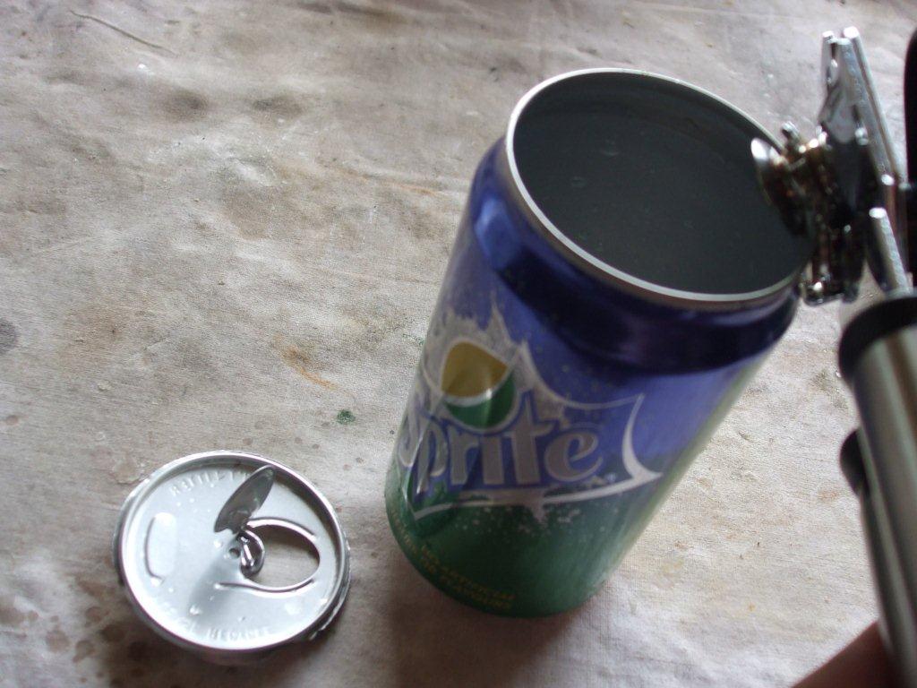
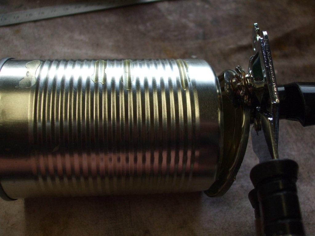
1/ Using a can opener remove the inside top part of the can. The piece I removed is shown in the pic on the right. Hold the can opener at the same angle as in the pic.
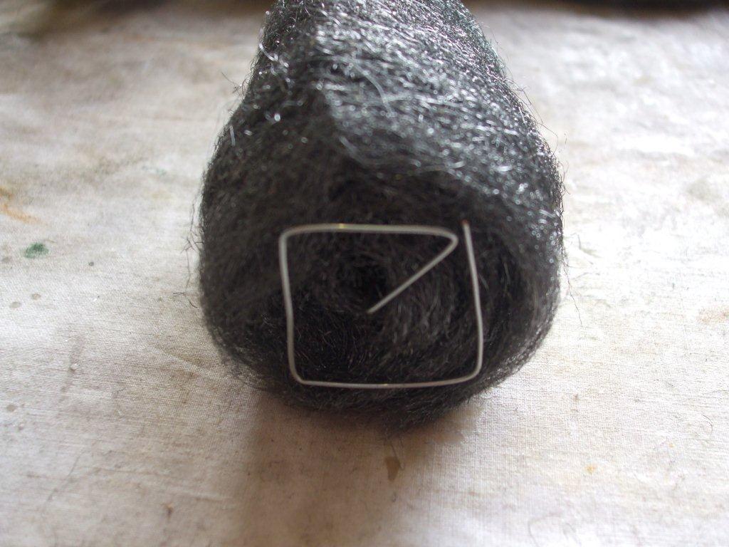
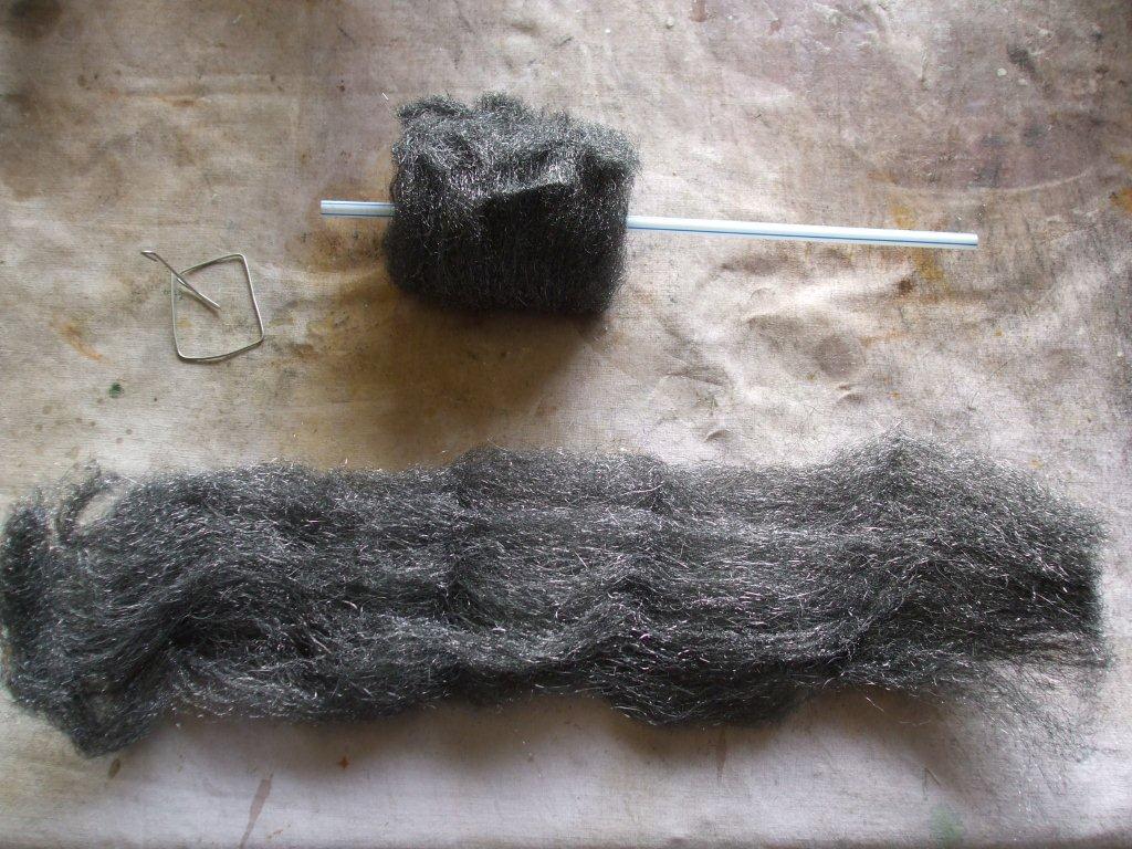
3/ To the right shows how I rolled up some wire wool around a drinking straw. The height was approx 70mm and the diameter was sufficient to fit snugly inside a coke can but still be able to slide up and down within it. The ability to slide is very important. The wire wool that I purchased came in eight bits and this happened to be the length and width of one of those pieces.
|
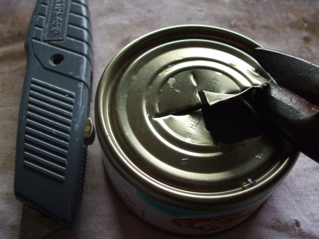
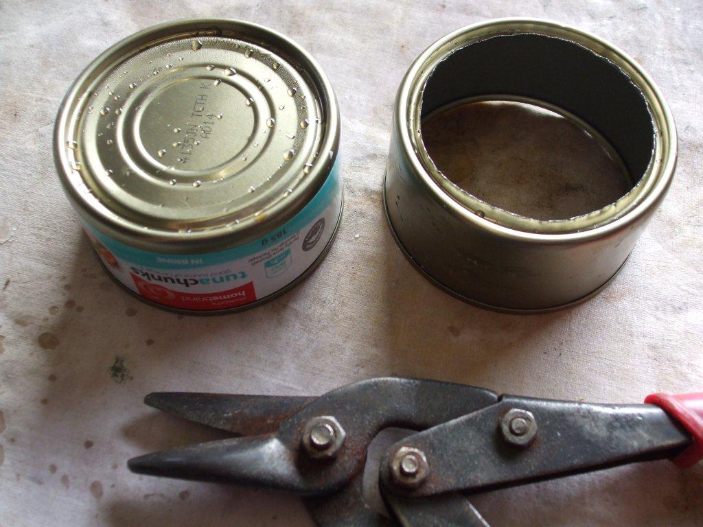
2/ Using a knife cut a large access cross in the bottom of the tuna can as seen on the left pic. This will help you get the tin snips in to cut the bottom out. The hole that you are cutting needs to be able to fit snugly around a coke can so you may need to come in from the tuna can edge with your cut.
You can see this more clearly with this picture on the left. Here I've shown a before and after shot. |
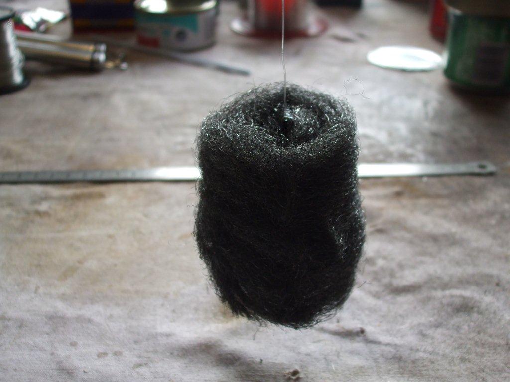
The above 3 pictures show how I bent up some wire to form a base with one end going up through the centre of the wire wool. Feed the wire through the straw to make life easier and then remove the straw. Bend the top over to form a loop and tie 200mm of fishing line to this loop. Suspend it by the fishing line and adjust it so it hangs evenly and straight.
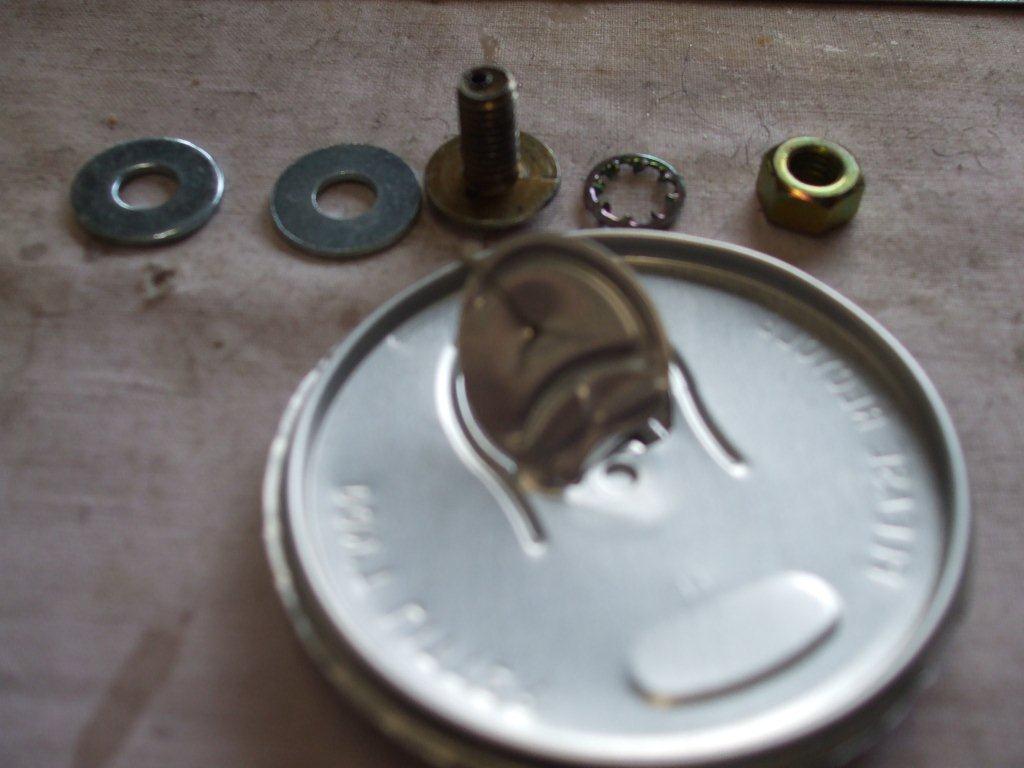
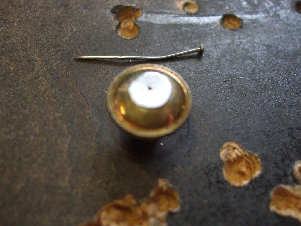
Here the above left pic shows the M6 bolt, nut and washers, I didn't use the shake proof washer in the end. The same pic also shows where I pushed a pin through the aluminium can top thing, you will need to cut around this hole to make a small piece to fit on top of the bolt head. This hole needs to be just big enough for the fishing line and no more.
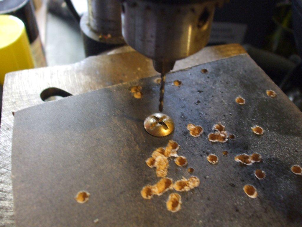
The above right pic shows the drilling of the 2mm hole down the centre of the bolt. I held the bolt by drilling a hole in a piece of flat wood and hammering the bolt into it, this kept it firm throughout the drilling. I had to unscrew it afterwards to remove it from the wood.
The above right pic shows the drilling of the 2mm hole down the centre of the bolt. I held the bolt by drilling a hole in a piece of flat wood and hammering the bolt into it, this kept it firm throughout the drilling. I had to unscrew it afterwards to remove it from the wood.
The above left pic shows the aluminum piece cut out around the small hole you made earlier with the pin. Glue this on top of the bolt head so that the hole is centered with the hole previously drilled in the bolt. Make sure the epoxy doesn't slowly make it's way into the hole and block it up.
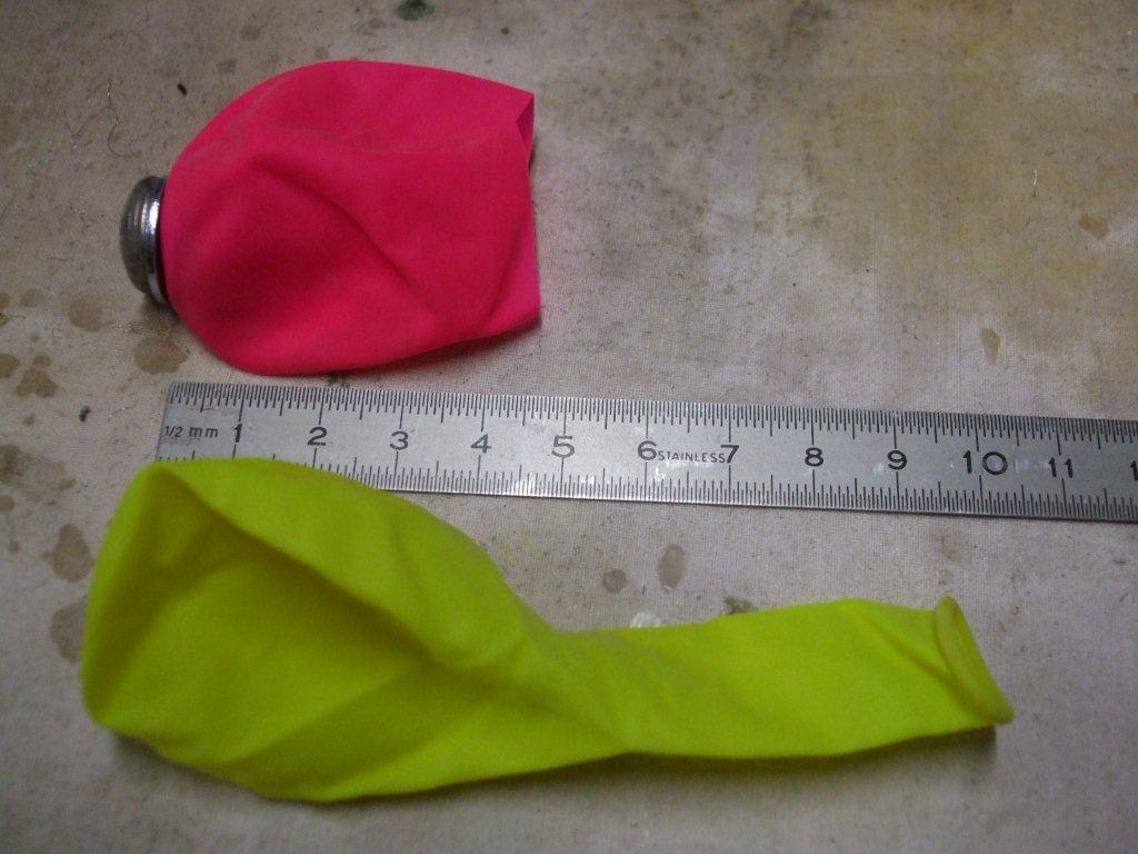
The above right pic shows how I cut the balloon, a nice pink one. When the glue has set on the bolt, pull the balloon over the bolt end so the end of the bolt lines up with the top center of the balloon. There's normally a small manufacturing dimple there to show the top center of the balloon. Make a very small cut or hole here and gently push the bolt through it. It should be very tight and a washer on either side of the balloon. Then put the nut on by hand as tight as you can.
The above right pic shows how I cut the balloon, a nice pink one. When the glue has set on the bolt, pull the balloon over the bolt end so the end of the bolt lines up with the top center of the balloon. There's normally a small manufacturing dimple there to show the top center of the balloon. Make a very small cut or hole here and gently push the bolt through it. It should be very tight and a washer on either side of the balloon. Then put the nut on by hand as tight as you can.
Now we can start to assemble some pieces together that we made earlier.
Get the coke can, the one that you took the top off of earlier, and carefully place the wire wool assembly into it so that it can easily slide up and down if you pull on the fishing line. Then pass the fishing line through the small hole in the bolt head of the balloon diaphragm and fit the balloon diaphragm over the neck of the coke can so that it looks like the picture on the right.
Tidy the balloon and push and pull it around so that it is centered. Then pull the fishing line up so that when slackened you will have a slight dip in the balloon as shown in the picture. It must be like this, do not make it tight as a drum skin, have another look at the video to show why it needs this slack.
Finish it by putting an elastic band around the neck, if you didn't cut too much off the end of the balloon then it may be tight enough anyway. Or if it is loose then you roll the neck part of the balloon that you cut off earlier into an elastic band and use that.
Double check that the wire wool will easily slide up and down inside the can when the fishing line is pulled.
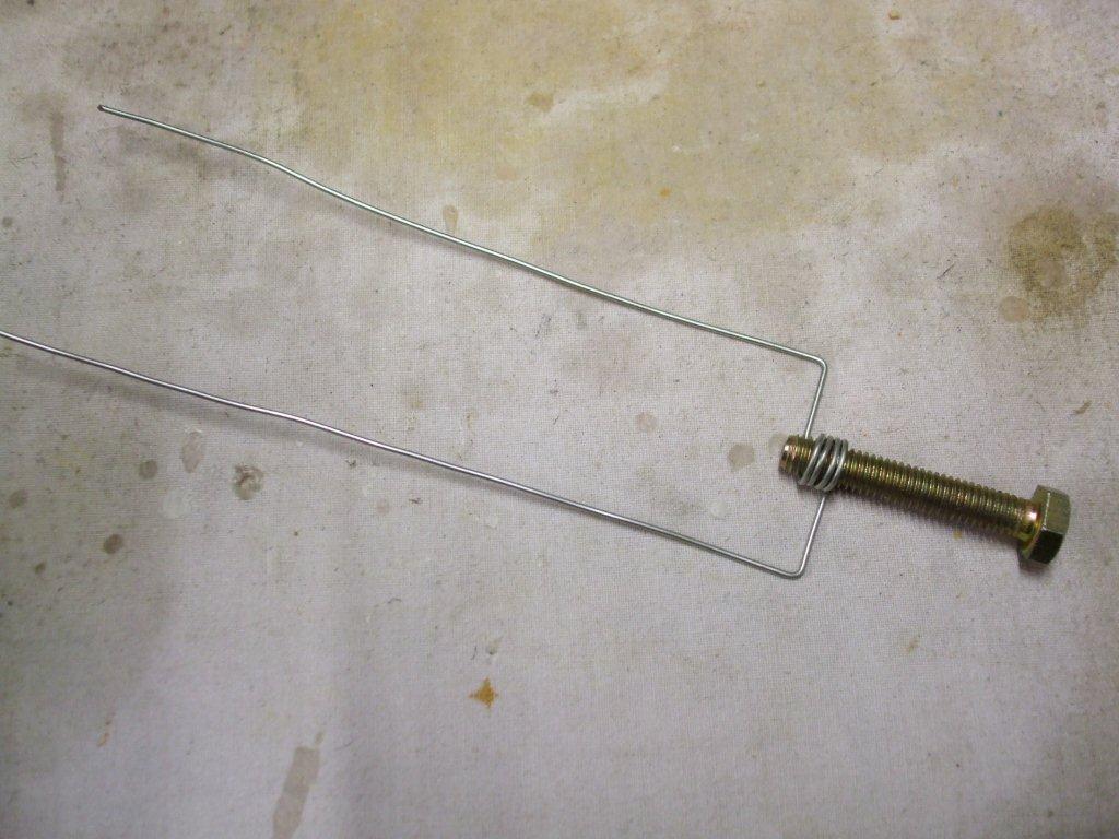
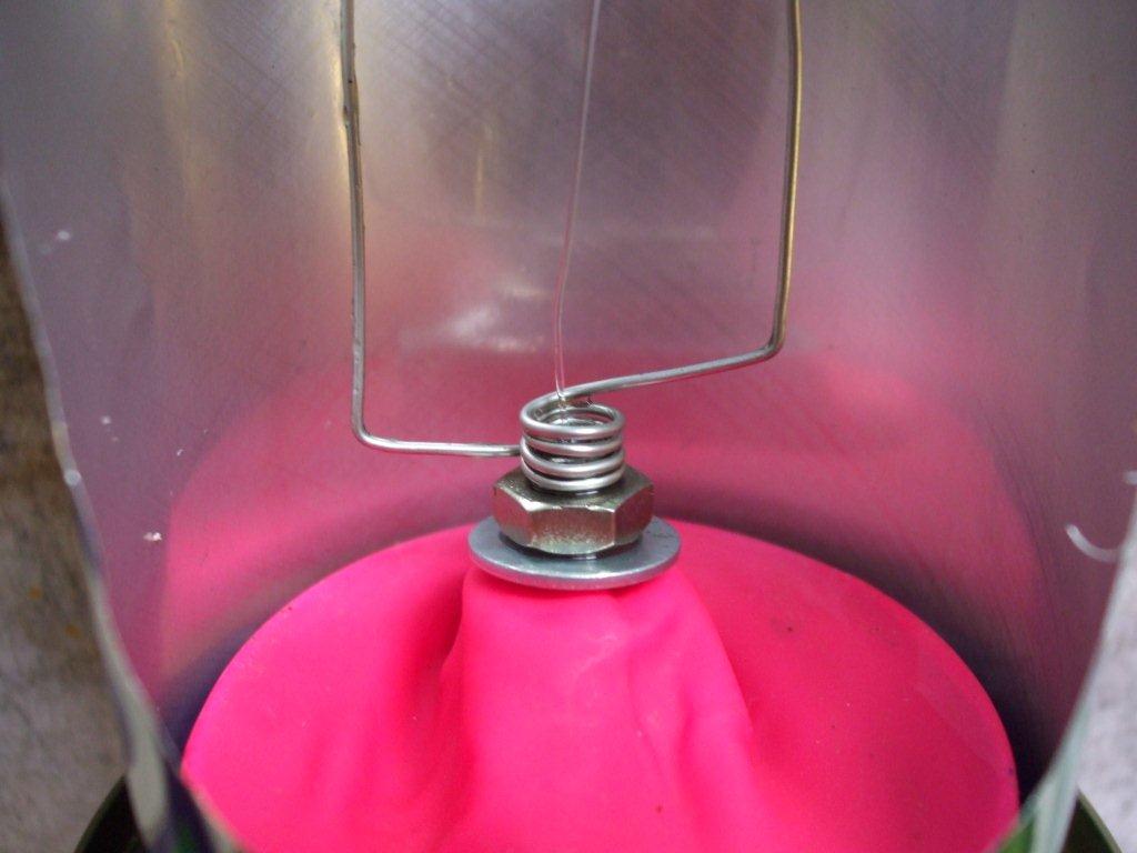
Wrap some wire tightly around a spare M6 bolt, about 4 wraps is enough. Then bend the legs so it looks like the above left picture.
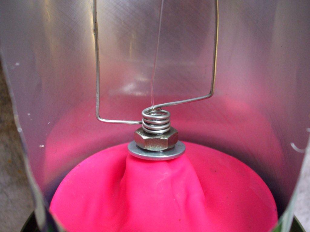
Now screw this onto the bolt in our diaphragm assemble so it looks like the above right picture.
Now screw this onto the bolt in our diaphragm assemble so it looks like the above right picture.
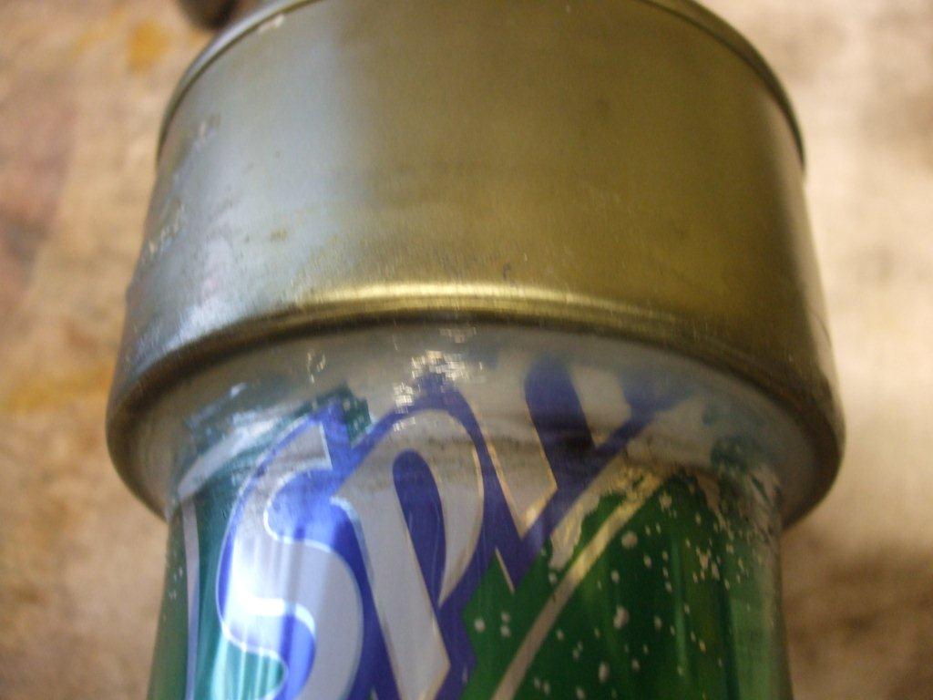
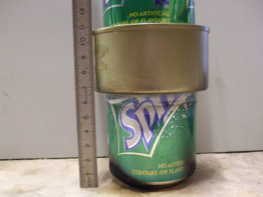
Now it's time to finish off this lower assembly by sealing the tuna can from earlier onto our coke can, the can with the balloon diaphragm. You can't see it in the above pics but the top of the tuna can does not line up with the top of the coke can, it lines up with just a bit higher than the coke can shoulder but before the top. I hope that makes sense. This needs to be sealed with whatever you have at hand, I used silicone sealant to make the join water tight. When finished the tuna can will be filled with cold tap water to keep the top of the coke can cylinder cool whilst the bottom of the coke can cylinder is very hot.
|
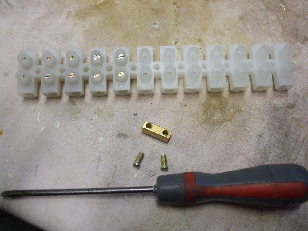
Here is that electrical choc block I mentioned in the parts list, just unscrew the screws and the brass core should just fall out. Remove 6 of these, I have seen many ways to connect the fishing line and wire to the cam shaft, one way was to use spade crimps which have a small hole in the spade end, they seemed to work well but I liked this idea better. The main reason was that it gives you an easy way to adjust the system but I also liked it because it was an ingenious solution using simple components. These plastic choc blocks are also called terminal strips and they are very cheap, less than $5 NZD each.
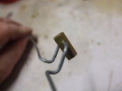
Drill a 2mm hole through 3 of these brass terminals so the wire cam shaft can pass through it as shown in the picture below left so the screw holes are facing forward. |
Now we need to bend up some wire to make that cam shaft. This may look intricate and fiddly but it really is very easy. First you must start with a straight piece of wire, to straighten it secure one end to something solid (a vice handle maybe) and pull it so it stretches just the tinniest bit, it should be nice and straight now.
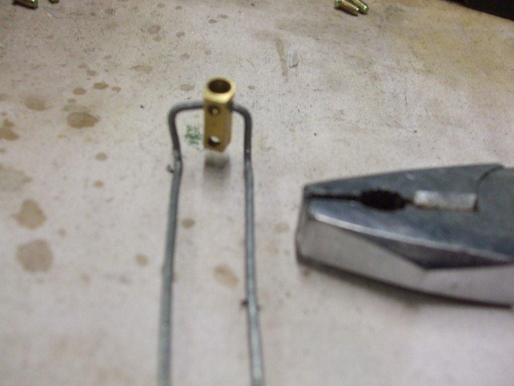
Using a pair of pliers bend the wire and insert one of the brass terminals like the picture above left. I just bent the wire around the end of my pliers to start with which produced an overall outside width of 16mm and an inside gap of around 12mm. It still a letter 'U" at this point, I hope you are still with me so far.
I then bent the 2 legs at 90 degrees, again with an overall length of 16mm to the outside of the bend so it looked exactly like the above left picture. This will be the center bit of the cam shaft shown below.
I realize now that explaining how to do this is not so easy, so I'm going to make it slightly easier by stating that the pliers I've used so far have jaws that are 10mm wide, when bending the wire around these it produces the dimensions referred to earlier.
For the next bends and most of the left and right bits of the cam shaft I used some needle nosed pliers with a jaw width of 5mm, bending them around these jaws seemed to work well for the shorter straight bits.
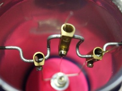
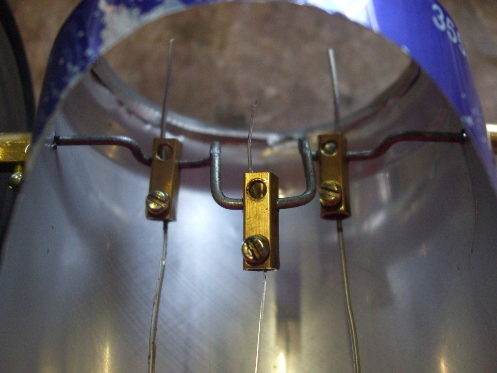
The finished cam shaft is shown in the pic on the right, don't forget to insert the brass terminals and have the screw holes facing all the same way.
All these bends are either done by wrapping the wire around a 10mm or a 5mm wide pair of plier jaws.
By doing this you should end up with something that looks similar to this picture.
Spin it around in your fingers to identify any kinks that need to be removed, spend a bit of time here trying to get this to run fairly straight. The one in the video is a little bent.
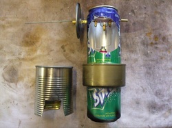
The next thing to do is to cut out the top coke can.
First cut out the top in the same way as you did with the lower can.
Then we need to mark out the 2 cam shaft holes and the large viewing window. I done this by wrapping a piece of A4 paper around the can, where it overlaps I marked it and trimmed off the overlapping paper so the 2 ends butt up to each other. Mark the paper at the same height as the coke can. Remove the paper and lay it flat, trim off the excess height so the paper is the same height as the can. The longest length of this paper should now be the circumference of the can, so go ahead and measure and mark the 2 cam shaft holes on the paper, the holes should be equal distance from each other and just a few mm lower than where the coke can side starts to bevel in.
I then marked out a 70mm circle on the paper equal distance from the 2 cam shaft holes. The top of the circle is at the same height as the cam shaft holes. Use a compass or anything that is approximately 70mm in diameter to mark the hole with. Cut the hole out of the paper.
All these dimensions for cutting this can are not critical.
Wrap the paper around the can again and join the ends of the paper with a piece of tape to keep it on the can.
Pierce the can with a push pin (item 12 in the parts list) into each cam shaft hole that you marked out earlier, leave the pins in for now as they help keep the paper from moving.
Now we need to cut out the large front circle, use a knife to cut a cross in the middle of the circled area on the can so you can get in there with a pair of scissors and cut the can. It is surprisingly easy to cut the can with scissors and fairly easy to make a nice looking circle. Tidy up any sharp bits if there are any but because we used scissors the edges will probably be ok.
Remove the paper and enlarge both cam shaft holes with a 2mm drill.
The last thing we need to do to this can is to cut the bottom off, this can be done carefully with a knife just above where the can starts to bevel in towards the base. Be careful here, don't rush it and try not to crush or damage the can. The knife cut can be tidied up with scissors afterwards.
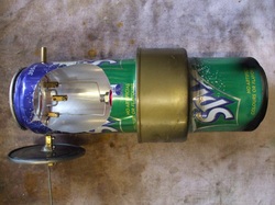
Now carefully press the top can over the bottom can, it will be a very tight fit. Check and straighten it to ensure both cans are in line with each other and it looks nice and straight when it's standing upright.
Install the previously made cam shaft whilst putting the 2 wires from the balloon into the brass terminals. You will have to trim off some of the length of the cam shaft to get it to fit inside the can, only cut off what you absolutely need to, and only cut it off of one end, the other end can stay very long for now.
The reason I mention to keep these ends as long as possible is that you will need to mount a fly wheel on one side and a brass terminal on the other. But you may also want to enhance this in the future with a fan blade or small alternator etc.
Ok, so you've managed to get the cam shaft in, next is to secure it loosely with 2 brass terminals either side so it's positioned evenly across the can.
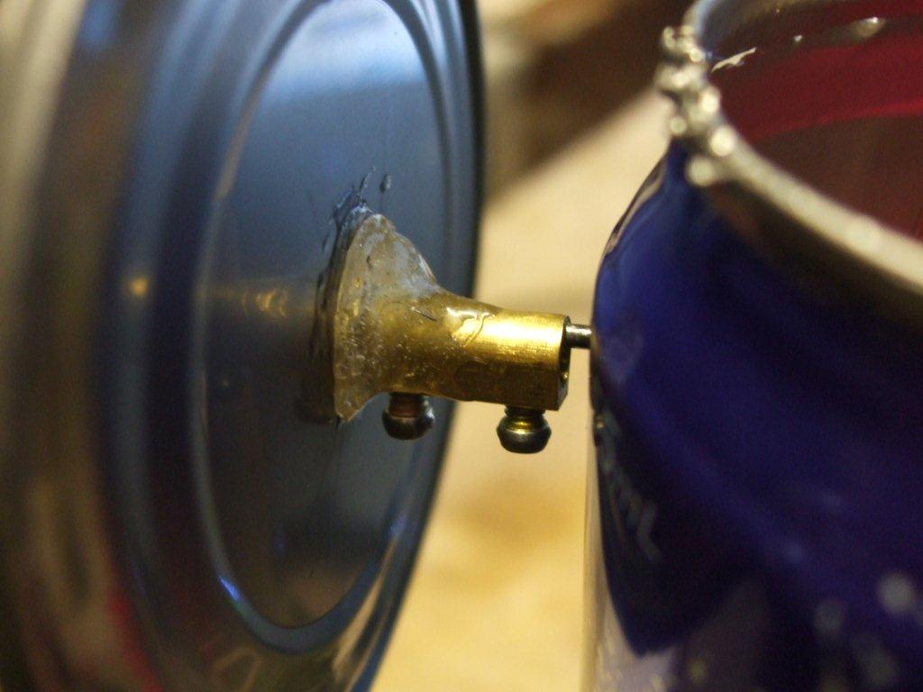
I used an old tin can lid for the fly wheel, I marked the center using a compass and drilled a 2mm hole in the middle. Then I used a 2 part epoxy glue to glue it to the brass terminal shown in the above right picture.
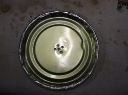
The glue didn't stick to the tin so I drilled a few more holes in the tin lid to give the glue something to bite into, this can be see in the pic above left. I also put another brass terminal on the other side of the fly wheel to help the fly wheel stay straight, especially while the glue sets, I ended up leaving it on there.
The glue didn't stick to the tin so I drilled a few more holes in the tin lid to give the glue something to bite into, this can be see in the pic above left. I also put another brass terminal on the other side of the fly wheel to help the fly wheel stay straight, especially while the glue sets, I ended up leaving it on there.
The next bit is the most important bit, it is this adjustment that will enable your engine to either work or fail dismally.
Feed the fishing line through the middle terminal, put the cam to it's highest position (the pic above left shows the lowest position). Now pull the fishing line so that the wire wool is approx 5mm from the top of the can and tighten the terminal. Turn the can shaft a few times and check if the wire wool slides up and down smoothly.
Now do a similar thing with the 2 balloon wires, but this time have the cam at it's lowest position as shown in the above left pic and pull the balloon wires up so that they pull the balloon as shown in the above right pic. This adjustment is one that you may need to repeat with a bit of trial and error to finally adjust your engine but hopefully if you've followed everything so far it should be enough to get it started.
Turn the cam a few times and check that it all works smoothly, and it's not too tight to turn it, in the balloon pic above right the balloon is not tight which allows the cam to move up and down fairly freely.
Almost finished, in this next bit we are going to make the fire box which the whole assembly sits on top of.
One end of the can has already been removed when you used it, this will be the top and we will leave this as it is. Using a can opener remove the bottom of the can as shown in the above left picture.
Using a pair of scissors or tin snips, at the bottom of the can, shorten the can so it is 95mm high. The reason I dine this was to bring the tea light flame nearer to the bottom of the coke can and therefore make it much hotter.
When assembled the lower coke can fits snugly into the top of this can, what I have is a gap from the bottom of the coke can to the floor of 35mm. Check and adjust yours to be about the same.
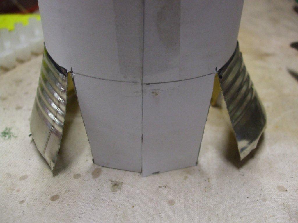
Next we need to cut some air intakes into the lower wall of the can, I cut 3 of these at 30mm high. Also 30mm wide at the top and 40mm wide at the bottom, enough to be able to slide your tea light through.
I marked out the cuts on a piece of paper in the same way as before shown in the above right pic, it's up to you, as long as you get the dimensions correct you can just cut it.
The picture above right shows the fire box before I cut off those bent out wing pieces.
These air intakes are a big part of the design, if they are too short your candle will be starved of oxygen and go out, if they are too big the flame could be accidentally blown out by a breeze.
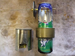
If you have something that looks like the picture on the left then you are finished.
Congratulations.
Now for the exciting part, light 3 tea light candles and slide them inside the fire box.
Sit the engine squarely on top of it.
Fill the tuna can with cold tap water to the very top.
Wait about a minute, all the time checking that the tea lights are still burning.
Then by hand bring the cam shaft to the top of it's rotation and gently spin it so that the fly wheel turns anti clockwise if looking from the left side in the picture on the left.
Do not worry if it doesn't start straight away, try it a few times and if it still doesn't start wait another minute and try again.
If you still can not get it going then the water may have got to hot/warm, so quickly pour out the water and replace it with cold tap water, wait 30 secs for the heat to build up and then try again.
If it really doesn't show any signs of wanting to start then you should adjust the balloon wires, make a small change to both wires and try it again. With a bit of trial and error as to whether the adjustment made it better or worse you should be able to get this going.
If you still have problems then double check the wire wool is still capable of sliding up and down by itself, the wire wool needs to rub on the inside walls of the can all the way around, but it must not be packed so tight to stop it easily sliding up and down.
For the exact information on how I got my engine started plus much more data then please go to the The Sterling Engine Results Page.
If you like our site then please click on the Facebook icon at the top right of this page, thank you.
For more information you can email us via our Contact Us page.


