I've got the whole day free so I'm going to start the wiring, I've been looking forward to this bit.
I still haven't received the accelerometer/gyro board but I can't wait any longer, there's enough work to be done without it for now.
Here is the wiring diagram in PDF format, page 1 shows how to connect 4 batteries together & page 2 shows just the 2 batteries.
I still haven't received the accelerometer/gyro board but I can't wait any longer, there's enough work to be done without it for now.
Here is the wiring diagram in PDF format, page 1 shows how to connect 4 batteries together & page 2 shows just the 2 batteries.
| markssupplies_wiring_diagram_self_balancing_scooter_v2.pdf | |
| File Size: | 200 kb |
| File Type: | |
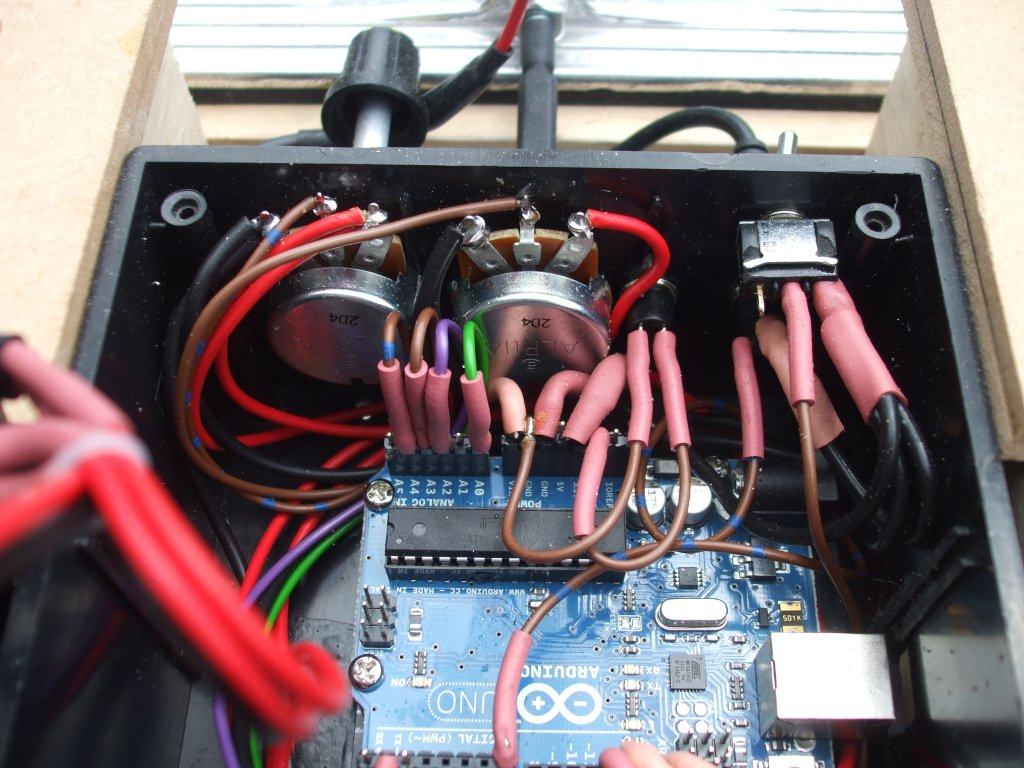
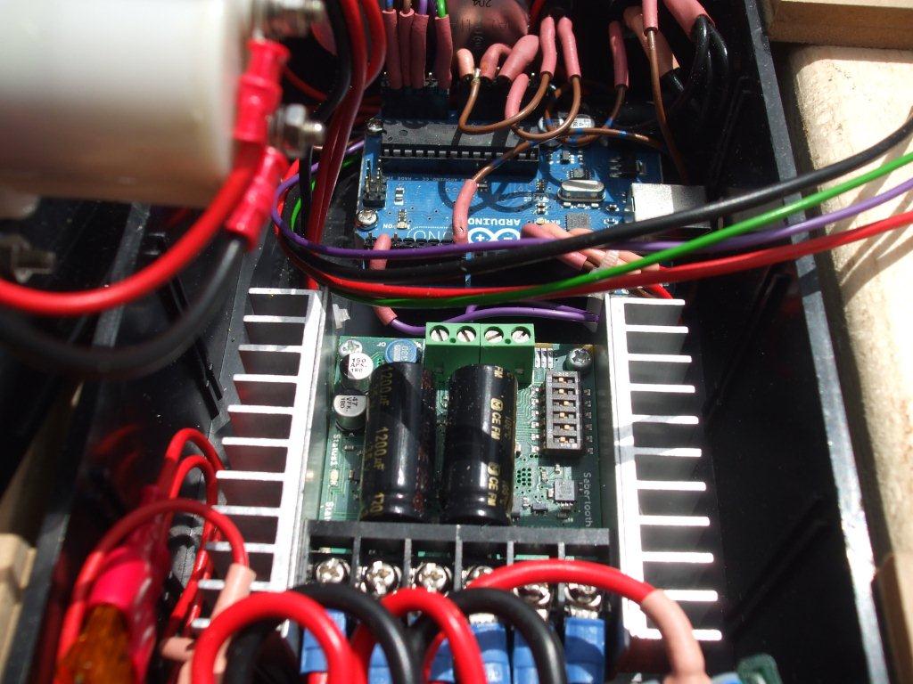
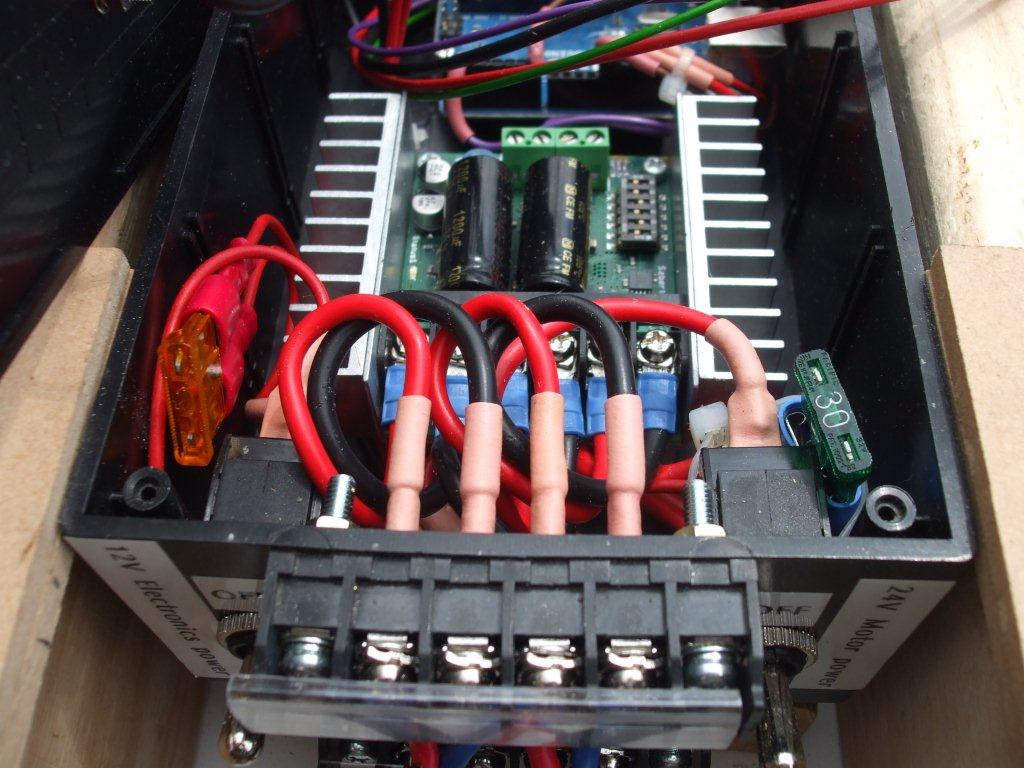
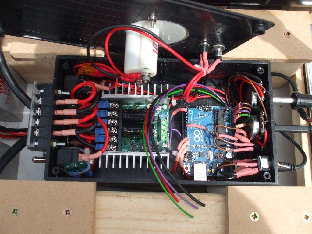
Here's what the wiring looks like, I've tried to solder every connection where possible instead of using crimps.
The lower right pic shows the 4 wires that are waiting for the accelerometer/gyro board, I've tried to leave space for the board next to the arduino but it may not fit, I'm sure I'll figure something out when it eventually arrives.
The top right pic shows 2 fuses, an orange one on the left & a green one on the right. These are just standard car fuses, the right one is 30 amps for the 24v & the left will be 1 amp for the 12v electronics. The lowest I had was 5 amp for now but I will replace it with a 1 amp soon.
The top left pic shows some of the arduino wiring, I wanted to have all the wires coming straight up from the board (see the 4 wires top left of the arduino coming straight up) but due to the DC meter & the switch & LED in the lid there was no room to do this for all the wires.
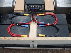
Here is how I connected the batteries, the 2 left batteries are connected in parallel (positive to positive & negative to negative). This keeps the voltage at 12v.
The same is done with the 2 batteries on the right.
Then the left pair & right pair are connected in series to create 24v (positive to negative).
The exact wiring is shown in the wiring schematic at the top of the page.
The same is done with the 2 batteries on the right.
Then the left pair & right pair are connected in series to create 24v (positive to negative).
The exact wiring is shown in the wiring schematic at the top of the page.
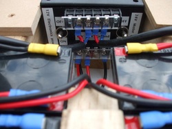
This shows a closer view of the connection of the batteries & the top 2 cables are from the motors.
I've added 2 switches here so I can independently turn off the 12v & 24v. This will be useful for testing.
I've used one of those label printers to label everything on the box.
I've added 2 switches here so I can independently turn off the 12v & 24v. This will be useful for testing.
I've used one of those label printers to label everything on the box.
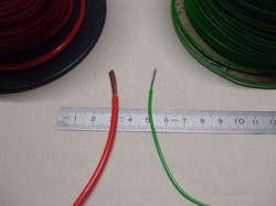
This should give you an idea of what size wire I used, I've also added some information regarding wire size at the bottom of the wiring diagram.
The wiring for the motors should be much larger than the 12v electronic control circuit wiring.
If you are unsure of what size wire to use for your 24v motor circuit then try to match the wire size that is already connected to your motors.
The wiring for the motors should be much larger than the 12v electronic control circuit wiring.
If you are unsure of what size wire to use for your 24v motor circuit then try to match the wire size that is already connected to your motors.
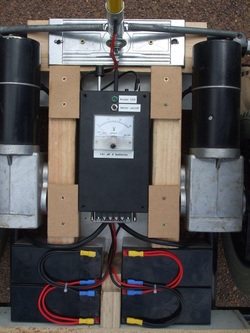
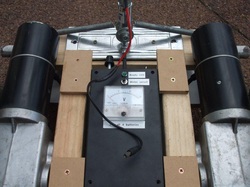
This shows how the box & batteries fit in with the rest of the scooter.
The pieces of wood either side of the box do not need to be fixed, they just sit there wedged in between the motors & the box. The right piece of wood would need to be removed to access the USB port.
I've screwed a couple of bits of MDF on top of the wood to increase the height slightly only because I never had any scrap wood wide enough.
I've also added a scrap piece of board at the back of the scooter, it sits on top of the metal frame & is fixed to the centre piece of wood that divides the batteries.
That centre piece of wood is screwed to the wooden base plate.
The board at the back is slightly higher than the batteries to allow for the wiring, the height matches the height of those MDF pieces mentioned earlier.
I've added a plug onto the end of the dead man switch wires that go to the handle, this plug fits into the front of the box.
I added this so I can easily remove the upright handlebar pole thingy, could be handy if I want to put it into the car.
I cut the plug off of a wall mounted phone charger (called a wall wart in the US) that I no longer use.
When buying the socket to mount onto the box I would recommend taking the plug to ensure it matches as there are many plug & sockets that look compatible but do not fit.
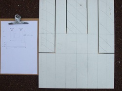
Here I'm part way through cutting out a top to fit over the scooter. What I needed was somewhere to put my feet but still be able to see the DC meter & access the front of the box.
The 305mm measurement in the picture was adjusted to 310mm after I had taken the photo.
I still intend to replace this top with that aluminium checker board plate I bought earlier but this old piece of scrap board will get me through the testing phase.
Actually this board & the piece I used for the base was an old desk top, it's only cheap chip board but it is very easy to work with, especially when I keep having to adjust the motor positions to keep the scooter balanced (which is why that measurement changed earlier).
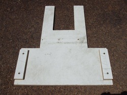
I added a couple of bits of wood on the back to stop the board sliding backwards.
The motors stop the board slipping forwards.
I've purposely made this whole cover to be a very tight fit as I didn't want any rattles.
It may need fixing down at some stage but it seems just fine as it is for now.
The motors stop the board slipping forwards.
I've purposely made this whole cover to be a very tight fit as I didn't want any rattles.
It may need fixing down at some stage but it seems just fine as it is for now.
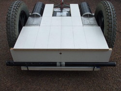
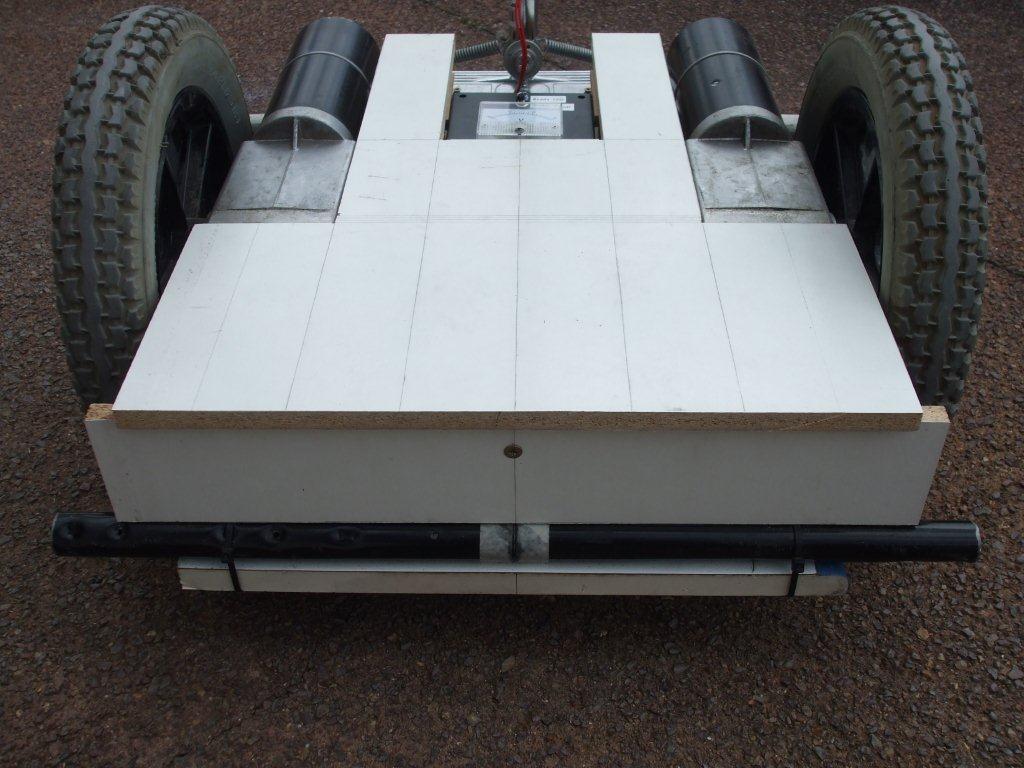
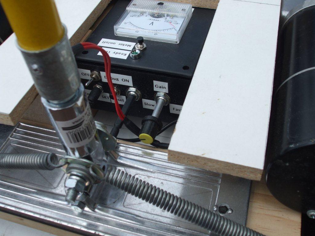
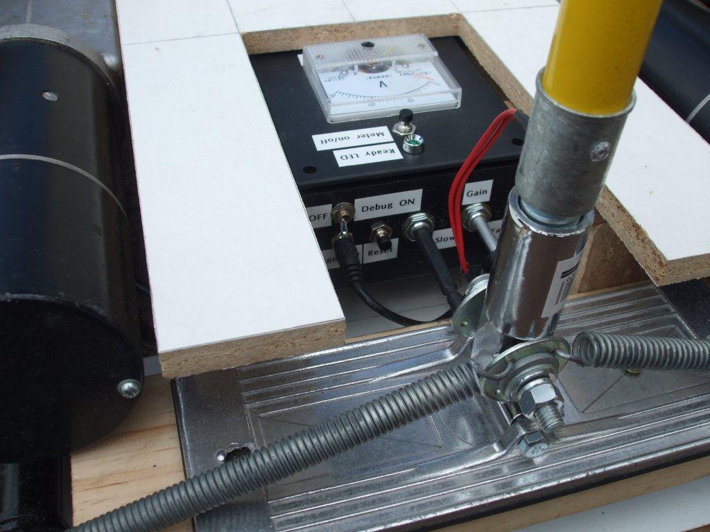
Here it is fitted, it actually fits very well & there is no need for any fixings.
The meter can be seen & the front of the box is easily accessible.
The meter can be seen & the front of the box is easily accessible.
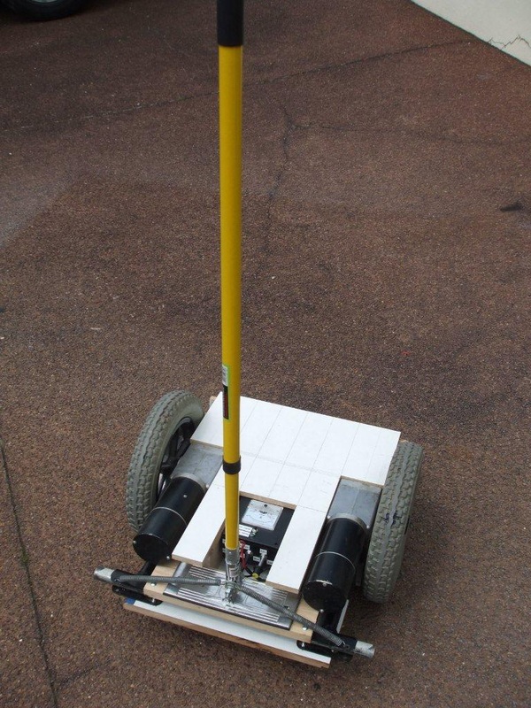
Below is what it all looks like so far.
It sits there perfectly balanced without any electronics, at least for now.
What I would do is slide the motors along on the tubular frame so that the scooter is perfectly balanced but the next time I checked it the balance had changed. I put it down to not fixing the motors tight enough but after re-balancing it & tightening the motors the balance still changed.
I thought maybe the bench I was working on was not level & maybe that had something to do with it but I dismissed that as clutching at straws.
More straw clutching later, and I started to think that maybe this had something to do with the inside workings of the gearbox but it didn't really make any sense.
It turned out that the problem was that the bench I was working on was not level!!
It makes sense now, because I was balancing the scooter by eye I was actually eying it up in relation to the flat surface of the bench.
So be warned, balance it on a level flat surface, it makes a huge difference & unless you've experienced this yourself then you will probably not fully embrace how important this is.
If you like our site then please click on the Facebook icon at the top right of this page, thank you.
For more information you can email us via our Contact Us page.


