
Self Balancing Scooter Day 6
29th October 2012
4 hours |

|
More to come soon.
Probably not until Saturday 27th.
OK so Saturday came & went & I didn't get chance to do anything on this project. The good news is that I've fixed a power steering problem on my sons car & fixed the electric windows on my wife's car & manged to get these & my trailer passed the NZ warrant of fitness test, which is a bit like the UK's MOT test for vehicles but this is every 6 months & it includes trailers as well.
The electronics eventually arrived but due to the accelerometer/gyro board not being available I chose another type which I'm now regretting.
The original one that I had wanted communicated via 2 analogue wires which made the communication & programming of the micro processor relatively simple. But the new IMU3000 that arrived communicates via a serial bus which is better but unfortunately my skills in this area are limited. I did however hook it up & eventually get it to work but somewhere along the process it stopped working & I've not been able to revive it.
So I'm now waiting on the original 5DOF to be delivered, these things are relatively inexpensive but it's the waiting that is a problem.
I've had a look at the best way to mount & wire all these things & I will be putting all the electronics into a box & having all or most of the switches, LEDs & volt meters mounted on the outside of the box.
Below is the parts list for the complete project:
| markssupplies.com_parts_list_for_self_balancing_scooter_v1.2.xlsx |
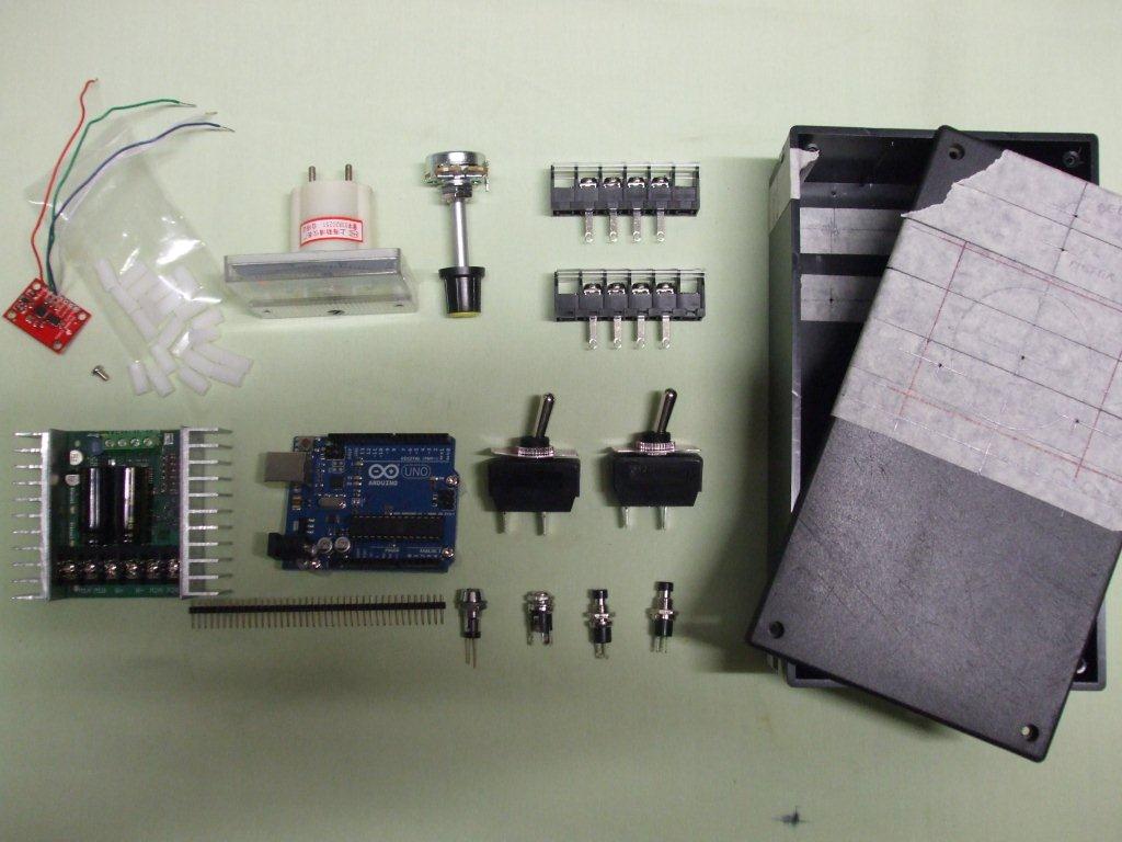
I've taken a photo of some but not all of the parts below. The red board is the accelerometer/gyro combined on one very small board that no longer works, it will be replaced by a 5DOF board. There is more information on this combo board on the Day 10 page.
It would be much better to mount the volt meter, pots & the ready LED somewhere that can be easily seen & accessed but I'm not sure where. I'm torn between making a quick working model & making the best design possible so I may have to make some compromises.
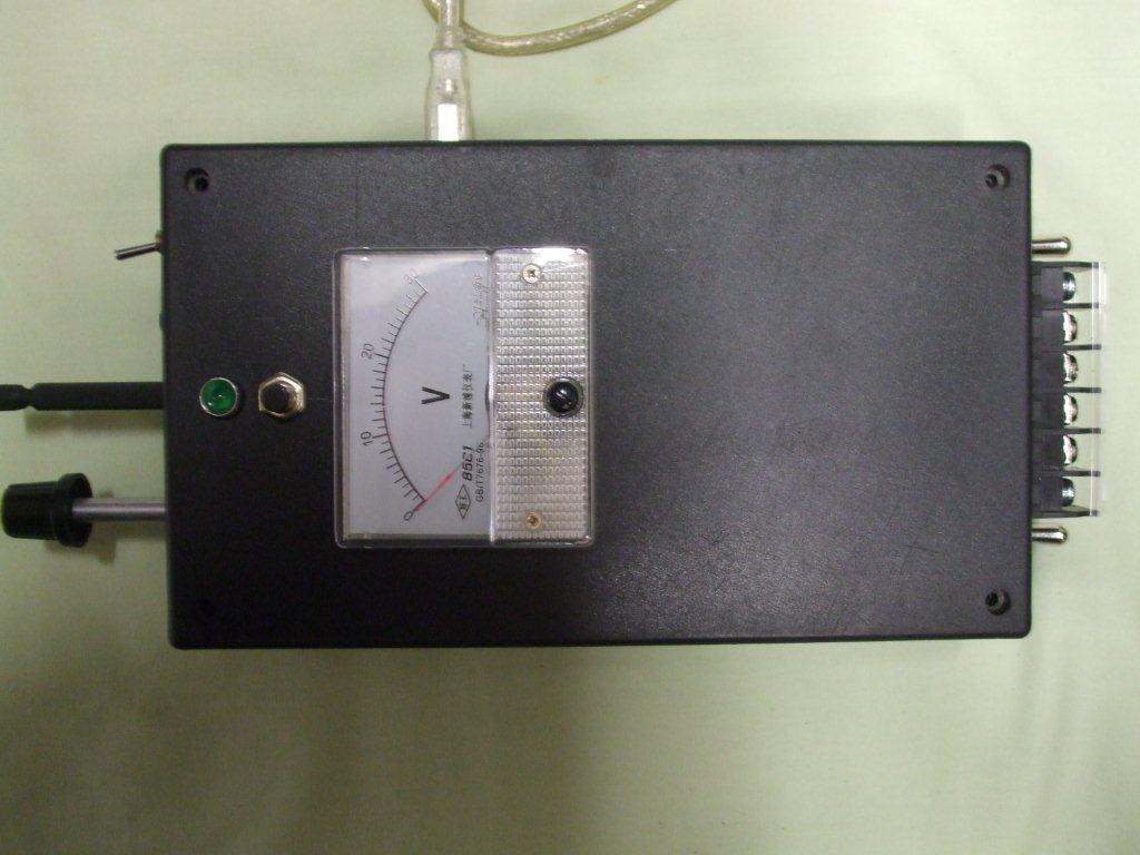
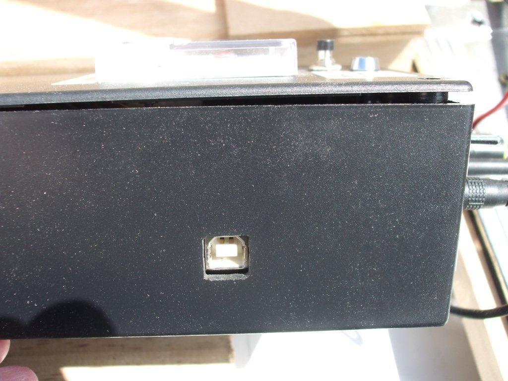
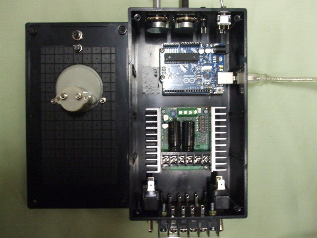
Here's some pics below of what I ended up doing, in the end I put everything in the one box, it's a tight fit but I think I can make this work.
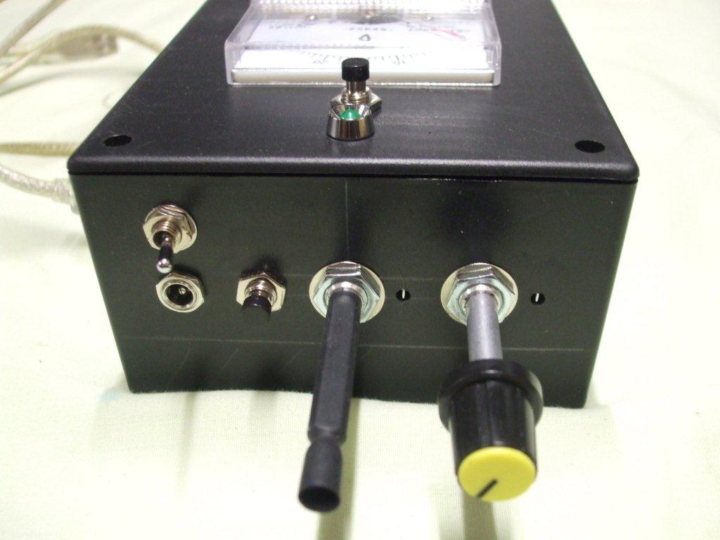
The lower left pic shows the steering pot with heatshrink tubing over it, I was going to connect this pot to the steering bolt with a rubber sleeve but there was too much flexibility in the joint so I tried the heatshrink & it works really well. I will have to secure it to the bolt with a cable tie but for now I'm leaving it as it is because it makes it easy to turn the pot by hand for testing without moving the steering pole.
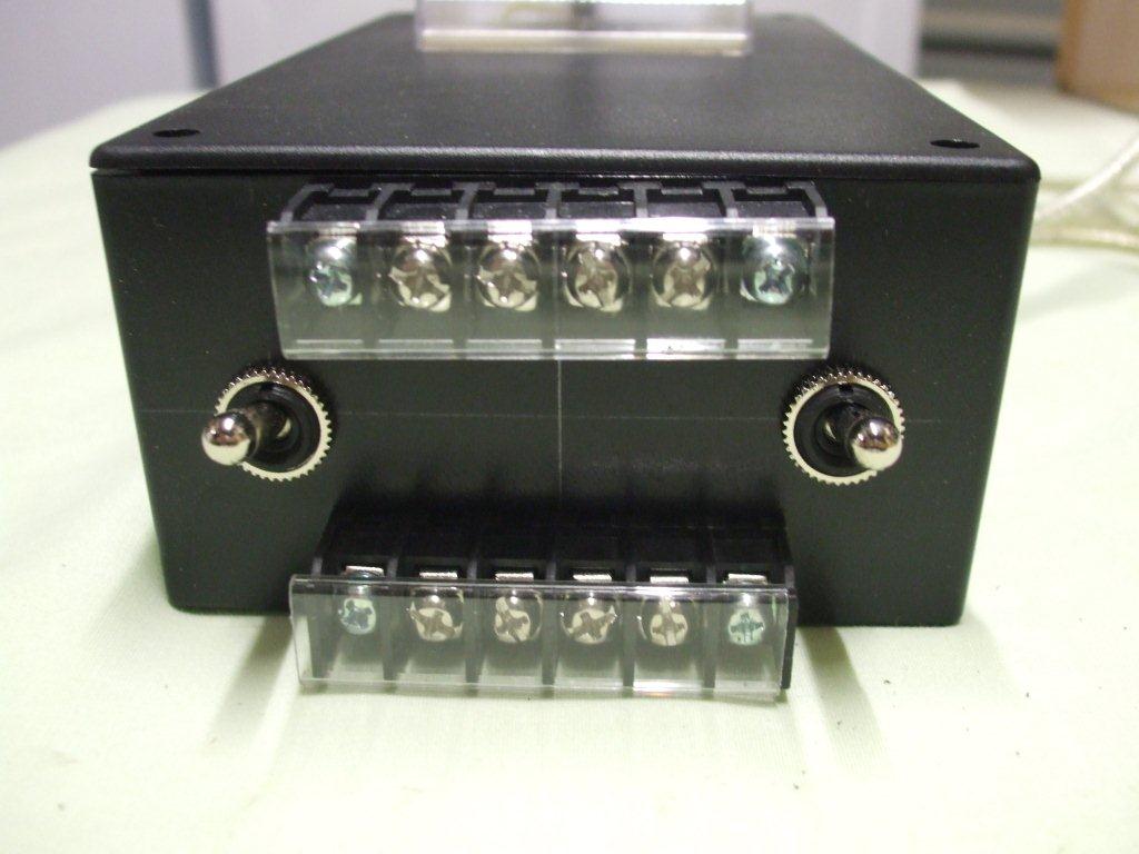
The lower pic shows the back of the analogue DC meter, I've designed it's position so the meter connections line up with the space between the Arduino & Sabertooth board, as I said before it is all very tight but it I think it will be ok.
The Arduino & the Sabertooth board are both mounted on plastic pillars, a bag of the pillars is shown in the pic above, you can get threaded or unthreaded pillars & I went for the threaded pillars which makes the build a little easier.
The Sabertooth board is designed to get hot & it has this large metal heat sink to dissipate some of that heat, my concerns are that mounting it inside a plastic box will not help it cool down. I would much rather mount it without pillars to a metal box but a metal box will make it far more difficult to mount the DC meter & the USB socket hole so I'm going for a plastic box for now (plus a metal box would have been $50 compared to $10). I have seen these boards mounted in similar plastic boxes with no problems so it should be ok but definitely something to look out for later.
If you are making your own all I can recommend here is that you mark everything out very carefully, it would be easy to rush this bit. Maybe it's just me but if one of the switches or maybe the meter was slightly out of centre or not aligned to the other components it would bug me every time I look at it.
Here's some pics below of what I ended up doing, in the end I put everything in the one box, it's a tight fit but I think I can make this work.
The lower left pic shows the steering pot with heatshrink tubing over it, I was going to connect this pot to the steering bolt with a rubber sleeve but there was too much flexibility in the joint so I tried the heatshrink & it works really well. I will have to secure it to the bolt with a cable tie but for now I'm leaving it as it is because it makes it easy to turn the pot by hand for testing without moving the steering pole.
The lower pic shows the back of the analogue DC meter, I've designed it's position so the meter connections line up with the space between the Arduino & Sabertooth board, as I said before it is all very tight but it I think it will be ok.
The Arduino & the Sabertooth board are both mounted on plastic pillars, a bag of the pillars is shown in the pic above, you can get threaded or unthreaded pillars & I went for the threaded pillars which makes the build a little easier.
The Sabertooth board is designed to get hot & it has this large metal heat sink to dissipate some of that heat, my concerns are that mounting it inside a plastic box will not help it cool down. I would much rather mount it without pillars to a metal box but a metal box will make it far more difficult to mount the DC meter & the USB socket hole so I'm going for a plastic box for now (plus a metal box would have been $50 compared to $10). I have seen these boards mounted in similar plastic boxes with no problems so it should be ok but definitely something to look out for later.
If you are making your own all I can recommend here is that you mark everything out very carefully, it would be easy to rush this bit. Maybe it's just me but if one of the switches or maybe the meter was slightly out of centre or not aligned to the other components it would bug me every time I look at it.
|
|
If you like our site then please click on the Facebook icon at the top right of this page, thank you.
For more information you can email us via our Contact Us page.