Sourcing The Technical Stuff
I have found some great information from this site www.rediculouslygoodlooking.com thanks JohnDavid400.
I now know what components will work well together so it's just a matter of getting them, if I can negotiate a discount for MarksSupplies.com customers then I will add direct links of where you can buy all the items but for now I will list what I have purchased:
1/ Arduino UNO R3 USB (This is the Micro controller)
2/ IMU 5 Degrees of Freedom (This board has both the accelerometer & gyro)
3/ Sabertooth 2 X 25 motor controller (This provides the power to both motors)
These items came to a total of $250 NZD so I'm getting close to my budget already but with these parts & the motors plus some batteries that I already have then there should be no more expensive parts to buy.
While I wait for these items to be delivered I will make a start on building the support frame.
Building the Support Frame
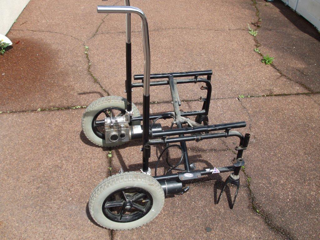
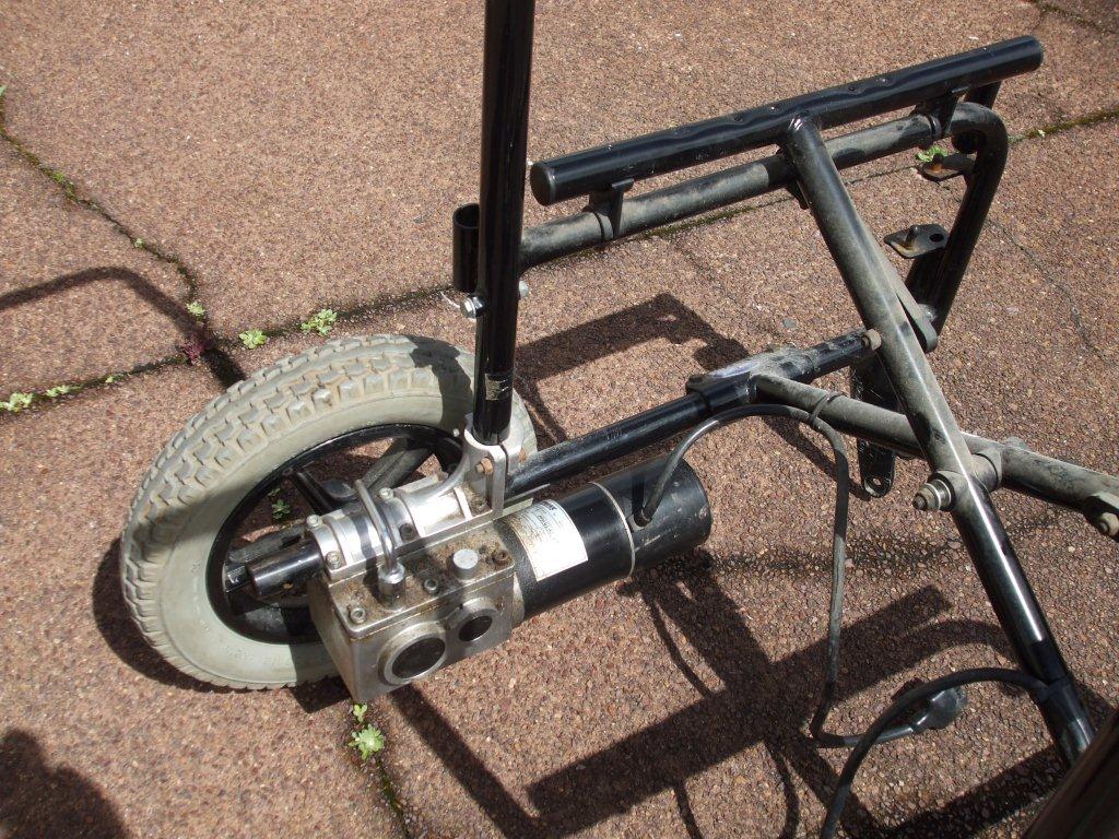
Here are some pics of what the wheelchair looks like when it's stripped down.
It would seem a good idea to use the wheelchair frame some how to build the scooter frame. What I need is a solid square frame that I can secure the motors to. The motors are already designed to fit to the round tubular frame so it would be good to use this frame if I can.
And those shiny silver tubular handles are a push fit into the black tubular frame, they are secured with one bolt each. If I had known this when I collected the chair then I would have removed them so it would fit in my vehicle easier. Anyway, now I know they fit inside each other I'm starting to think how I could use that in the design, could it be part of the upright steering, not sure but worth remembering.
At first glance it looks possible to make a frame but when I start to look at it in more detail there are many problems.
In the pic below I've put something together that might work, it uses the 2 connecting scissor action cross struts that connect the left & right side of the chair together. I will connect them with some old pipe I had in the garage & see if it looks feasible as a strong design.
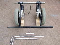
I've added an old galvanised pipe across one end (top of photo), it fits well & can be bolted in place later.
I'm going to connect the other ends together by putting a push fit tube inside to span the join. I thought I could use that shiny tubular handle to fit inside the tube but it was too tight & wouldn't fit. I spent 30 minutes with a piece of the tubular handle grinding the diameter down very slightly using a bench mounted grinding wheel.
At the bottom of the photo it shows a complete handle plus the one I cut a short piece off of & ground down.
I marked the middle of this tube & then inserted it between the 2 black tubes to span the gap. I made this sound like it just slipped in but it took a lot of effort with a lump hammer (builders hammer). I was anxious that it didn't get stuck half way & I couldn't get it in or out any further but I eventually got it to fit really well. It's such a tight fit that it probably will not move but to be sure I will add a couple of self tapping screws later.
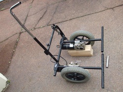
Instead of using that old galvanised tube shown above I experimented with trying to use more of the wheelchair frame. It certainly looked possible but it would have been a lot more work trying to cut & grind off the welds. But it's worth showing what could be possible, especially if unlike me you do not have a handy piece of pipe in the garage.
This could be a design that you would prefer if you were going to have a fixed upright handle & steer with a pot on the handlebars.
However I'm going to try to design the upright handlebar to move left & right & have this movement connected to a pot that send the data to the micro controller which will adjust the motors to turn.
You can also see the shiny pipe on the right that I used to connect the 2 black tubes together.
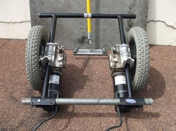
Here is what the frame looks like, the pipe is now joined at the top of the photo & the motors are bolted on. I will add a couple of self tapping screws later to stop the motor assemblies turning on the pipe, although they seem very secure already.
The clamps that hold the motors to the frame have an upright bit on them that I'm not using at the moment but I will keep it for now as it maybe useful if or when I add some guards over the wheels.
I've cut the finished frame to size so that the end of the tubes on all 4 corners extend to the same width as the outside of the tyres.
The motors at this stage can be slid along the tube for optimum balance later.
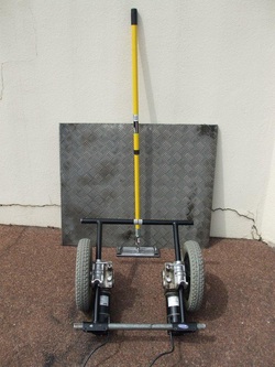
At the back of the photo is an aluminium sheet with a grip pattern on it, otherwise known as checker plate. I picked this up from a local metal recyclers for $15 NZD, it's very strong & also light. It could do with a clean towards the end of the build but it's good enough for now. I'd like to cut it & fit it to the frame but I can't do this until I know where the motors will end up so it will have to wait. I may have to put an old piece of board across the top for now so I can experiment with the balance to get the best place for the batteries, motors, upright handle & a person.
Talking of handles, the yellow thing at the back of the photo is an extendable decorating tool for cleaning or sanding floors & ceilings, or at least I think that's what it's for. I bought it for $30 NZD because I think it would make a good steering handle. The main pole is fully adjustable & the connection to the plate at the bottom uses a universal coupling so it can move in any direction. However I only need it to move left & right so I'll have to alter it some how. As for the adjustable pole, I would have to add a bolt to lock it down after adjustment or it may loosen during use. I'm still not totally convinced that using this yellow thing is the way to go but I thought I'd mention it seeing as it's in the photo.
Talking of handles, the yellow thing at the back of the photo is an extendable decorating tool for cleaning or sanding floors & ceilings, or at least I think that's what it's for. I bought it for $30 NZD because I think it would make a good steering handle. The main pole is fully adjustable & the connection to the plate at the bottom uses a universal coupling so it can move in any direction. However I only need it to move left & right so I'll have to alter it some how. As for the adjustable pole, I would have to add a bolt to lock it down after adjustment or it may loosen during use. I'm still not totally convinced that using this yellow thing is the way to go but I thought I'd mention it seeing as it's in the photo.
Removing the electrical brake
The electronics still haven't arrived so I'm going to look at removing that electrical brake I mentioned in the video on day 1.
A proper electrical brake will stop a motor by changing the polarity of the power going to the motors, but the brake I'm going to remove is just a solenoid (a little electrical piston) that locks the gears or motor into place, which is what the clicking sound is in the video.
I had thought of keeping the brake & automatically turning it on & off when the scooter is turned on & off but it's not like it's going to roll off somewhere because the motors will be engaged so if I can remove it I will.
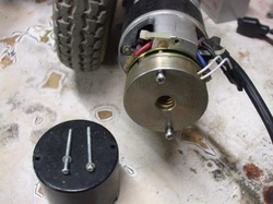
I removed the 2 long screws & pulled the black cap off, it slid off fairly easily.
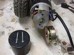
Then I removed the next 2 screws which held the brake on. The brake is the gold coloured thing.
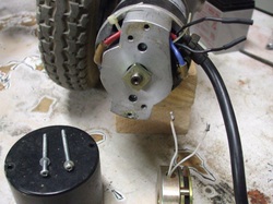
I cut the wires that went to the brake & put heat shrink over the ends of the wire that were still attached to the motor flex. Some insulation tape would also be fine here instead of heat shrink. The wires will not be connected to anything so they should be safe but I covered them anyway as you never know what may happen in the future.
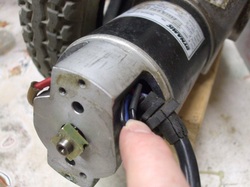
Carefully tuck those wires back out of the way.
It can be a little tricky to line the screws up so I marked a line on the outside of the motor which lines up with the screw hole. Then I slid the end cap back on so the holes lined up.
Now you can secure it with the 2 long original screws that you took out earlier.
It can be a little tricky to line the screws up so I marked a line on the outside of the motor which lines up with the screw hole. Then I slid the end cap back on so the holes lined up.
Now you can secure it with the 2 long original screws that you took out earlier.
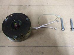
Here are the items that you should have removed, 2 screws & the entire brake assembly.
It would be prudent to keep these bits just in case you need it one day, maybe when you get older you might want to make a wheelchair out of a scooter!
Attach the wires to a 12v battery & you can see how it operates by moving in & out.
It would be prudent to keep these bits just in case you need it one day, maybe when you get older you might want to make a wheelchair out of a scooter!
Attach the wires to a 12v battery & you can see how it operates by moving in & out.
Removing the gearbox lever
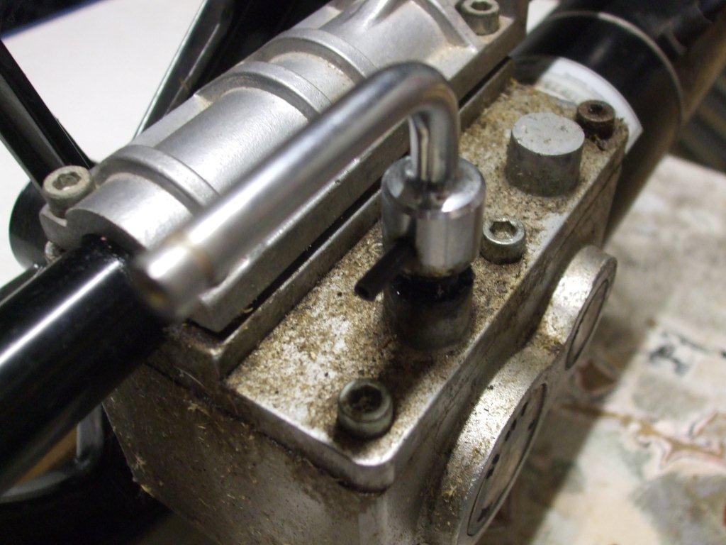
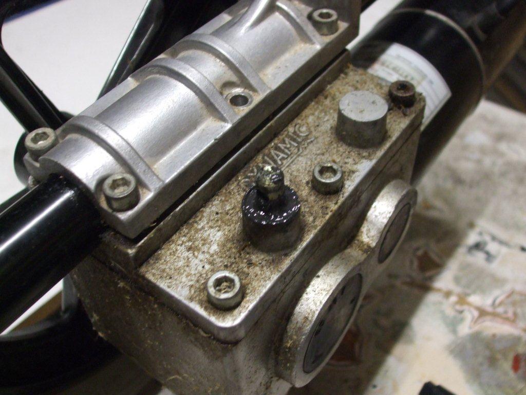
This lever will either engage or disengage the gearbox, on a wheelchair it can be useful if you want to push the wheelchair instead of using the motors. You may want to do this if you have run out of battery power.
Well the same is true of course with the scooter, if you are out & about & the batteries run out of power then how will you get the scooter home. It will be too heavy to carry, you maybe able to push it but the wheels will not really want to turn because they are connected to the gearbox & motor.
So what do you do? The levers protrude into the area where you want to mount the foot plate.
I guess on some models you can turn the motor upside down so the levers are at the bottom but this would affect the ground clearance. Also I'm not sure if this would affect any lubrication in the gearbox, probably not but I can't be sure.
So it would seem that I have 3 choices left:
1/ Remove the lever & hope I never need it one day.
2/ Cut a hole in the foot plate to allow the lever to poke through.
3/ Remove the lever but put a hole in the foot plate so that you could use it in an emergency.
I'm going for option 3, with the intention of storing the lever on the scooter some where.
The lever is held in place with a roll pin, I gently tapped it out & removed the lever. I used a flat ended punch for this, not everyone will have the right tool but what ever you use try & make sure it has a flat end. Don't use a screw driver or you will damage the pin, you may want to use this pin in an emergency one day!
If you like our site then please click on the Facebook icon at the top right of this page, thank you.
For more information you can email us via our Contact Us page.


