Update 12th Jan 2013.
The accelerometer/gyro board arrived just before Christmas but I hadn't had chance to install it until today so thanks for your patience.
I installed it on top of the capacitors of the sabertooth, I put a bit of rubbery foam on top the capacitors & then put the board on top & secured it all with one cable tie.
I installed the board & the scooter worked straight away, no coding or signal problems.
I had it on blocks on the bench to test & found a couple of easy to fix minor problems. I had to transpose the wiring to one of the motors so it rotated in the correct direction & I also had to transpose the steering pot wires so it turned left when the steering arm went left.
Apart from that it works fine.
I've made the changes in V2 of the wiring diagram (which can also be found on the Day 7 page) to reflect those 2 problems and also added some notes to help you if you also have similar issues.
Some of these problems could have been fixed within the code but I think it is better for everyone to work with the same code & make the changes in the wiring. That way we can email & swap code and everything will still work the same for everyone.
As for riding it, I've had a couple of quick tries & I'm a bit wobbly. The scooter does what it suppose to do but I'm all over the place. I'm unsure if I need more practice or if it is because the angle (and therefore the speed) is limited due to the length of the scooter or maybe too much weight above the axle or above my waist.
The main thing at this stage is that it works.
More to come soon.
Update March 2013.
I've had some time recently to tweak the arduino code to see if that would help my wobbly performance on the scooter. I'm glad to report that the problem was not my riding skills but more my software skills, anyway with a few tweaks here and there in the software the scooter is perfect and very easy to ride.
I have documented on the Day 10 page exactly why and what I did in the software but for now here is a video of my very first ride after getting the software dialed in to suit my design.
I have uploaded my tweaked V4 code that works for the IDG655 gyro & ADXL335 accelerometer onto the previous Day 8 page .
To ride the scooter I first removed the cover & turned on both the 12v & 24v switches.
As soon as the arduino has power it will calculate the zero level angle so the scooter needs to be held level for a few seconds after power on.
In the video mine was not level so after I replaced the cover I leveled the scooter & then pressed the reset button which made the arduino calculate the zero level angle again.
Then I held the engage (dead mans switch) down, the software will only engage the motors if the scooter is level when it is pressed. With the motors engaged then you can just step on it & gently tilt the handle bar forwards.
You will need to keep the dead mans switch pressed until you stop, if you let go whilst you are moving then the scooter will stop abruptly which may make you leap off the front. Don't worry it's not that bad, but I'm sure there are ways of getting hurt, just like riding a bike, so be careful.
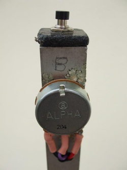
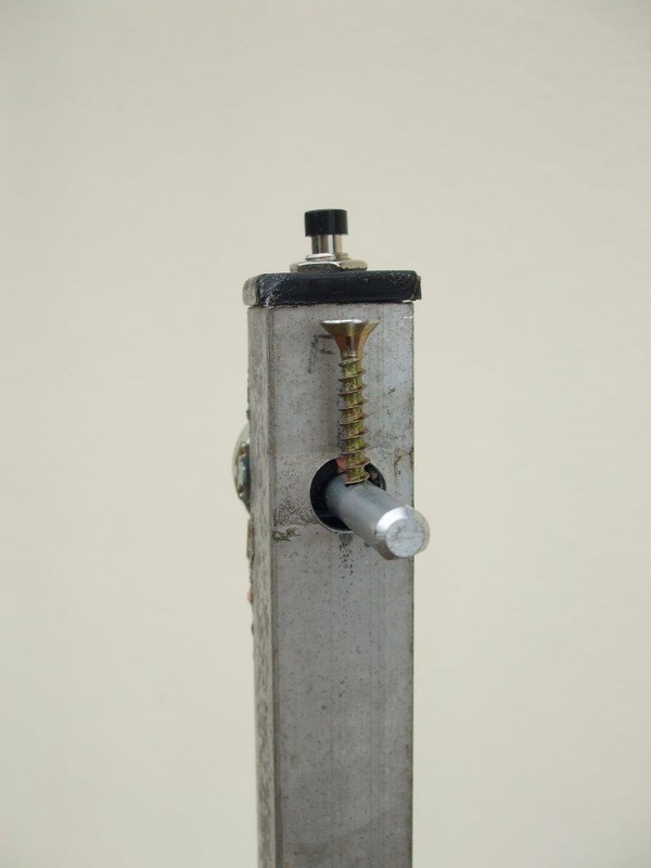
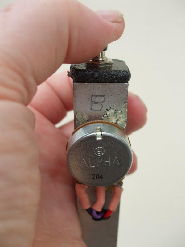
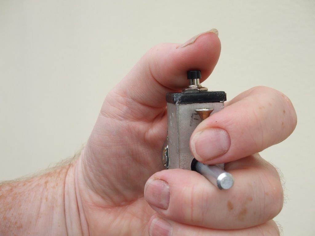
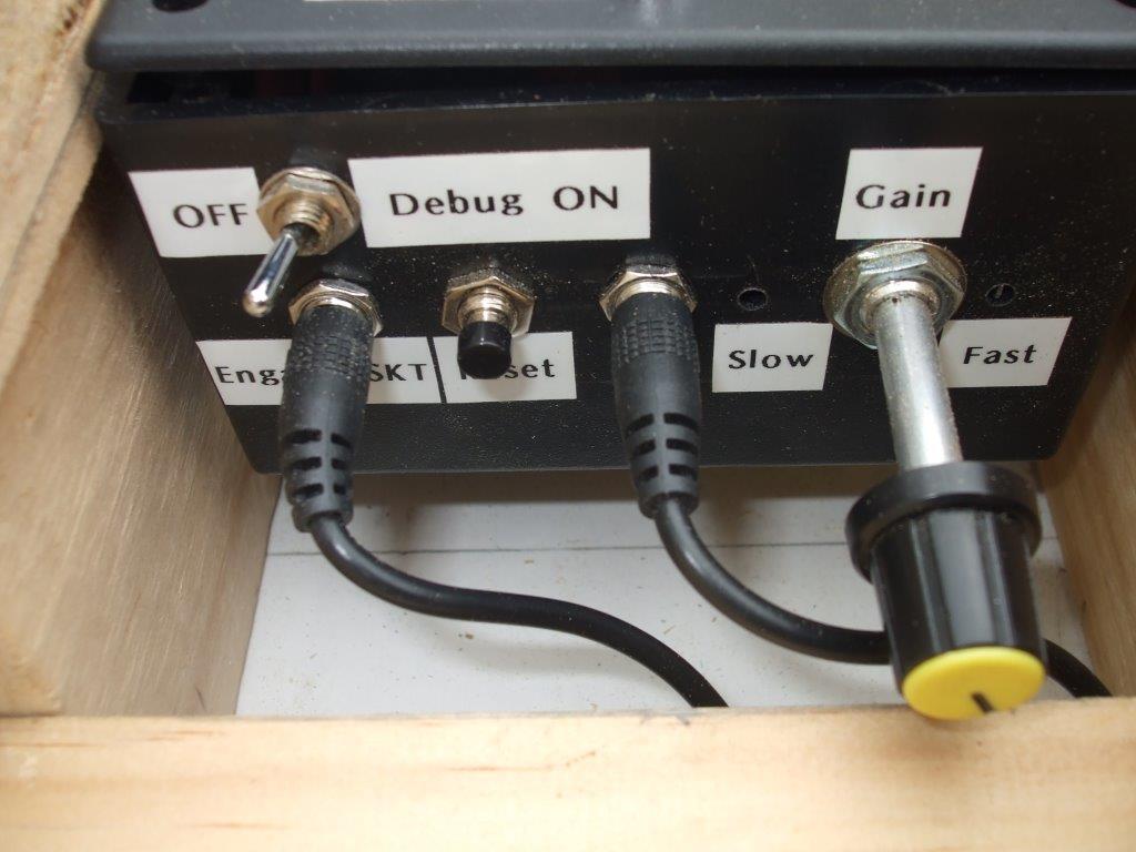
I also found that the upright handle bar needed to be much more rigid than my original design so for now I replaced it with a fixed rigid length of aluminium. It was actually part of an old TV aerial, it is hollow so I could route the wires up inside it. I removed the steering pot from the control box & mounted it along with the dead mans switch on the top of the handlebar as shown in the picture below. The switch & steering pot are mounted so they can be easily operated with one hand, I would recommend this setup as it is surprisingly comfortable & easy to use.
|
The handle bar is an old piece of hollow aluminium that used to be a TV aerial, it could do with something a little bit stronger as I'm sure this will bend or break over time. But for now I'm up & running. I am already thinking about version 2 which will have the same wiring & coding but I will make the frame much shorter so I can get better ground clearance on hills.
|
I added another jack plug & socket for the pot wires. I removed the original steering pot from the control box & used the same hole to mount the jack plug & socket.. The pot needs 3 wires to work but one of them is a ground so I used the same ground from the dead mans switch, that way I only had to run 2 cables for the pot.
I used plug & sockets because it would make it easier to remove the handle bar for transporting in the car. Using one 4 wire plug & socket would be a better design but I had these handy + it gives me more options for the future. |
If you like our site then please click on the Facebook icon at the top right of this page, thank you.
For more information you can email us via our Contact Us page.


